


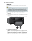


Chapter 3 Operation of Front Panel Indicators
22 4027620 Rev A
Initial Power Up, Calibration, and Registration (AC
Power applied)
The following chart illustrates the sequence of steps and the corresponding
appearance of the cable modem front panel LED status indicators during power up,
calibration, and registration on the network when AC power is applied to the cable
modem. Use this chart to troubleshoot the power up, calibration, and registration
process of your cable modem.
Note: After the cable modem completes Step 7 (Data Network Registration
Complete), the cable modem proceeds immediately to Normal Operations. See
Normal Operations (AC Power applied) (on page 24).
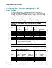
Front Panel LED Status Indicators During Initial Power Up, Calibration, and
Registration
Part 1, High Speed Data Registration
Step:
1
2
3
4
5
6
Front Panel
Indicator
Self
Test
Downstream
Scan
Downstream
Signal Lock
Ranging
Requesting IP
Address
Request High Speed
Data Provisioning
File
1
POWER
On
On
On
On
On
On
2
DS
On
Blinking
On
On
On
On
3
US
On
Off
Off
Blinking
On
On
4
ONLINE
On
Off
Off
Off
Off
Blinking
5
LINK
Off
On or Blinking
On or Blinking
On or
Blinking
On or Blinking
On or
Blinking
6
TEL 1
On
Off
Off
Off
Off
Off
7
TEL 2
On
Off
Off
Off
Off
Off
8
BATTERY
On – When battery is charged
Blinks – When battery charge is low
Off – When there is no battery in the unit
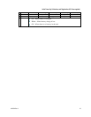
Front Panel LED Status Indicators During Initial Power Up, Calibration, and
Registration
Part 2, Telephone Registration
Step:
7
8
9
10
11
Front Panel
Indicator
Data Network
Registration
Complete
Requesting
Telephone IP
Address
Request
Telephone
Provisioning File
Restarting Voice
Service
Telephone
Registration
Complete
1
POWER
On
On
On
On
On
2
DS
On
On
On
On
On
3
US
On
On
On
On
On
4
ONLINE
On
On
On
On
On