


Data Sheet
© 2010 Cisco and/or its affiliates. All rights reserved. This document is Cisco Public Information. Page 3 of 8
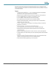
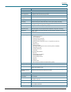
Figure 2. Model EPC2425 Front Panel (image may vary from actual product and specification)
Table 1. Front Panel Features
Feature
Description
Indicators
Power, DS, US, Online, Ethernet, Wireless Link, Wireless Setup, Tel1, Tel2
Color
Black, black lens, silver text
Branding
Cisco and model number
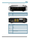
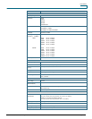
Figure 3. Model EPC2425 Back Panel (image may vary from actual product and specification)
Table 2. Back Panel Connections
Feature
Description
Power
Connector Color: Black
Connects the wireless home gateway to the DC output of the AC power adapter
Power Switch
Turns power on and off to the device (power switch provided on all products carrying the CE
mark)
Telephone 1 and 2
Color: Gray
RJ-11 telephone ports connect to home telephone wiring and to conventional telephones or fax
machines
Ethernet (1 – 4)
Connector Color: Yellow
Four RJ-45 Ethernet ports connect to the Ethernet port on your PC or your home network
Reboot EMTA
Power cycles the EMTA
Wireless Setup
Activates Wi-Fi Protected Setup (WPS), which allows you to add wireless devices to the wireless
network of the residential gateway
Cable
Connector Color: White
F-connector connects to an active cable signal from your service provider
Antenna (not shown)
Provides a communication connection for the built-in WAP