


1-9
Cisco IAD2430 Series Integrated Access Devices Hardware Installation Guide
OL-4234-05
Chapter 1 Overview of Cisco IAD2430 Series IADs
Physical Description and LEDs
Physical Description and LEDs
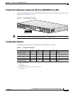
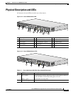
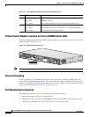
All interface slots and LEDs are on the rear of the chassis.
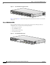
Figure 1-12 Cisco IAD2430 Series IAD
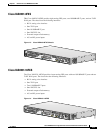
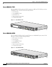
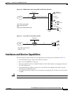
Figure 1-13 Cisco IAD2400 Series LEDs
1 Chassis ground connection 6 WIC/VIC slot 11 DC power input
1
1. This is not a redundant failover power supply connection. You must use either DC or AC.
2 RJ-21 connector 7 10/100BASE-T port 1 12 On/off switch
3 T1/E1 port 1 8 10/100BASE-T port 0 13 AC power input
4 T1/E1 port 0 9 AUX port
5 Compact flash slot 10 Console port
88828
2
3
4
7
8
9
10
11
12
13
6
5
1
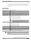
Table 1-3 Cisco 2430 Series IAD LEDs (Cisco 2432-24FXS shown)
No LED/Color Description
1 ACT—green
Status—green
Green indicates activity; when any of the 24 voice ports is active in
a call (off hook) or one of the analog ports is in use
Green when accessing IAD
2 CF (Slot 0)—green Green when accessing read or write function
95007
1
2
4
3