


6
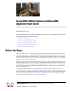
Cisco MCS 7890-C1 Business Edition 3000 Appliance User Guide
OL-25101-02
Connecting the MCS 7890-C1
Wall-Mounting
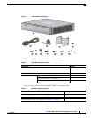
Perform the following procedure to mount the MCS 7890-C1. You use items from the wall-mounting kit
described in Table 3 on page 3.
Procedure
Step 1 Take the wall-mounting template and temporarily attach it to the wall on which you want to mount the
MCS 7890-C1. Attach the template to the wall so that the image of the MCS 7890-C1 appears in the
exact place where you want to mount the MCS 7890-C1.
Step 2 Locate the four dark circles on the wall-mounting template. Locate the lines that intersect inside these
dark circles. At each point where the lines intersect inside these dark circles, use a scratch awl or other
sharp pointed object to punch a hole through the wall-mounting template to mark the spot on the wall
where you want to drill a hole for a mounting screw.
Step 3 Remove the wall-mounting template from the wall. At each of the four spots you marked in Step 2, drill
a hole with a 0.3-inch-diameter (7.5-mm-diameter) drill bit. Drill each hole at least 1.37 in. (35 mm)
deep.
Step 4 Into each hole that you drilled in Step 3, insert a plastic anchor so that the opening of the anchor is flush
with the wall surface.
Step 5 Into each plastic anchor that you inserted in Step 4, insert a tapping screw. Screw in the tapping screw
so that there is 0.09 inches (1.5 mm) of space between the wall and the back of the screw head.
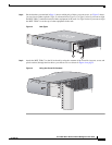
Step 6 Hang the MCS 7890-C1 on the wall. To do this, perform the following procedure:
a. Hold the MCS 7890-C1 in both of your hands with the Cisco logo facing you and the MCS 7890-C1
LEDs along the bottom edge.
b. Approach the wall that you inserted the tapping screws into.
c. Align the tapping screws with the round holes in the back of the MCS 7890-C1. Press the
MCS 7890-C1 toward the wall so that the heads of the tapping screws enter the round holes.
d. Move the MCS 7890-C1 slowly down the wall. Allow the MCS 7890-C1 to come to rest securely on
the tapping screws.
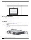
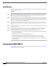
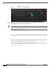
Connecting the MCS 7890-C1
Figure 5 on page 7 shows the various ports on the back panel of the MCS 7890-C1. See Table 4 on page 7
for descriptions of each of the numbers.