


2
Warning
Before connecting or disconnecting ground or power wires to the chassis, ensure that power is removed from the
DC circuit. To ensure that all power is OFF, locate the circuit breaker on the panel board that services the DC
circuit, switch the circuit breaker to the OFF position, and tape the switch handle of the circuit breaker in the OFF
position. Use a voltmeter to test for 0 (zero) voltage at the power terminals on the chassis.
Statement 196
Warning
This product relies on the building’s installation for short-circuit (overcurrent) protection. Ensure that the
protective device is rated not greater than: 5 A.
Statement 1005
Warning
A readily accessible two-poled disconnect device must be incorporated in the fixed wiring.
Statement 1022
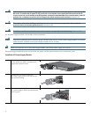
For all power-supply modules, review these caution statements:
Caution To prevent overheating and to maintain proper air flow, either an AC or a DC power-supply module or a module
blank should be installed in both power-supply module slots at all times.
Note Before you install the AC or DC power-supply module, turn off the power supply at its source.
The power-supply module slots are on the switch rear panel, and the power connectors are on the front panel.
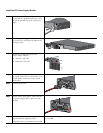
Install the AC Power-Supply Module
Step 1
Insert the power-supply module in the slot
on the switch rear panel, and align and
tighten the retainer screws.
Step 2
Connect the AC power cord to the
AC power input. Secure with the retainer
clip and the bushing.
Step 3
Turn on power, and verify that the
AC power-supply LED on the switch front
panel is green.
250447
PSU OK
A
C
250448
250449