


9
Supervisor Engine 720 Switch Processor and Route Processor Memory Installation Note
78-15538-02
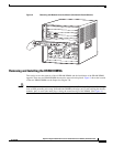
Installing the SP and RP Memory Upgrade Kit
Caution Always use an ESD wrist strap when handling the Supervisor Engine 720 or coming in contact with
internal components.
To remove the supervisor engine, follow these steps:
Step 1 Disconnect any network interface cables attached to the supervisor engine.
Step 2 Verify that the captive installation screws on all of the modules in the chassis are tight. This step ensures
that the space created by the removed module is maintained.
Note If the captive installation screws are loose, the EMI gaskets on the installed modules will push
the modules toward the open slot, reducing the opening size and making it difficult to reinstall
the module.
Step 3 Loosen the two captive screws on the supervisor engine that is to be removed.
Step 4 Depending on the orientation of the slots in the chassis (horizontal or vertical), perform one of the
following two sets of steps:
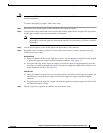
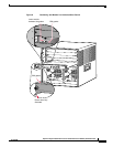
Horizontal slots
a. Place your thumbs on the left and right ejector levers, and simultaneously rotate the levers outward
to unseat the supervisor engine from the backplane connector. (See Figure 1.)
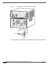
b. Grasp the front edge of the supervisor engine, and slide the supervisor engine partially out of the
slot. Place your other hand under the supervisor engine to support the weight of the module. Do not
touch the module circuitry. (See Figure 2.)
Vertical slots
a. Place your thumbs on the ejector levers located at the top and bottom of the supervisor engine, and
simultaneously rotate the levers outward to unseat the supervisor engine from the backplane
connector.
b. Grasp the edges of the supervisor engine, and slide the supervisor engine straight out of the slot. Do
not touch the module circuitry.
Step 5 Place the supervisor engine on an antistatic mat or antistatic foam.