


Send document comments to nexus7k-docfeedback@cisco.com
3-21
Cisco Nexus 7000 Series Hardware Installation and Reference Guide
OL-18634-01
Chapter 3 Installing a Cisco Nexus 7018 Chassis
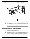
Installing the Front Door and Air Intake Frame
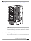
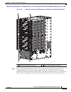
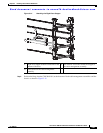
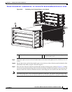
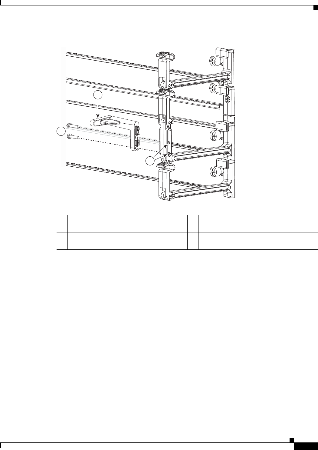
Figure 3-14 Attaching the Right Door Stopper
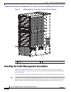
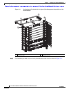
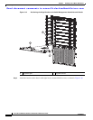
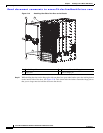
Step 3 Position the hinge bracket (700-28491-01) at the bottoms of both cable management assemblies and the
chassis as shown in
Figure 3-15.
192197
1
2
3
1 Right door stopper identified with an R on the
bottom of the base.
2 Two M3x10 screws that fasten the stopper to
the cable management assembly.
3 Screw holes on the cable management
assembly.