


Send documentation comments to nexus5kdocs@cisco.com.
4-6
Cisco Nexus 6000 Series Hardware Installation Guide
OL-15902-01
Chapter 4 Replacing Components
Replacing or Installing Power Supplies
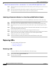
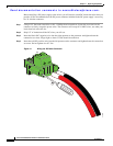
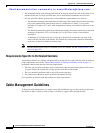
Before installing a DC power supply to the switch, you will need to attach DC connection wires that you
provide (10 GA recommended) to the DC power connector included in the DC power supply’s accessory
kit. To wire the connector:
Step 1 Using a 1/8” flat head screwdriver or No. 1 Phillips head screwdriver, loosen the set screws on the
connector to freely accept the power wires. The connector will accept 8-24 AWG wires, use what your
local electrical code calls for.
Step 2 Strip 1/2” of insulation off the DC wires you will use.
Step 3 Insert the black (DC negative) wire into the right aperture on the connector and tighten down the
connection set screw. Finger tight or about 3 ft./lbs should be sufficient.
Step 4 Insert the red (DC positive) wire into the left aperture on the connector and tighten down the connection
set screw. Do not tighten over 0.7 Nm.
Figure 4-1 Wiring the DC Power Connector
330338
2