


1-3
Platform Guide for Cisco Unified Videoconferencing 3545 System Chassis
OL-10282-01
Chapter 1 Cisco Unified Videoconferencing 3545 System Chassis Overview
Cisco Unified Videoconferencing 3545 Chassis Power Supply
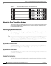
System Temperature Indication
The TEMP LED lights green to indicate that the temperature inside the chassis is within the acceptable
range. Red indicates overheating when the temperature reaches and/or passes the upper threshold.
Flashing green and red indicates that the temperature is close to the upper threshold. If the temperature
falls below the lower threshold, the LED remains green. The LED flashes green to indicate a sensor
malfunction. The upper and lower threshold levels are configurable in the web user interface of the MCU
and gateway.
Normal System Startup LED Indications
This section describes the normal LED indications that you should see when the system starts up.
At startup, the normal system monitor LED indications are as follows:
• The POWER LED indicator lights green and remains green.
• The ALARM, FAN and TEMP LED indicators flash twice, alternating between red and green. When
the platform initialization is complete, the LED indicators remain green.
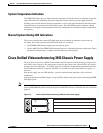
Cisco Unified Videoconferencing 3545 Chassis Power Supply
The rear panel of the Cisco Unified Videoconferencing 3545 chassis contains dual power supply units,
each with a power switch, an AC mains power connector and a safety fuse. The two PSUs use current
sharing to provide redundancy—if one PSU fails, the second PSU can handle the operational load of the
chassis until the failed unit is replaced. The PSUs are located to the left of the chassis rear panel., as
shown in .
Each power supply has one LED indicator—green to indicate normal operation, red to indicate a
malfunction.
In normal operation, both PSUs display a lit green LED, and the front panel system monitoring POWER
LED lights green.
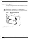
Note To enable PSU redundancy, connect both power inlets to a power source. If you connect only one power
cable, the POWER LED on the chassis front panel and the LED indicator on the PSU not in use will both
light red.
Figure 1-2 Cisco Unified Videoconferencing 3545 Chassis Power Supply
157276
POWER
POWER