


20-3
Cisco Network Modules Hardware Installation Guide
OL-2485-20
Chapter 20 Connecting T3/E3 Network Modules
T3/E3 Network Module LEDs
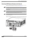
Tip When connecting the T3/E3 network module to a port adapter used in another router series, verify that
you are connecting the TX port on the network module with the RX port on the port adapter, and the TX
port on the port adapter to the RX port on the network module.
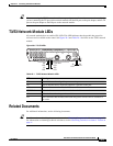
T3/E3 Network Module LEDs
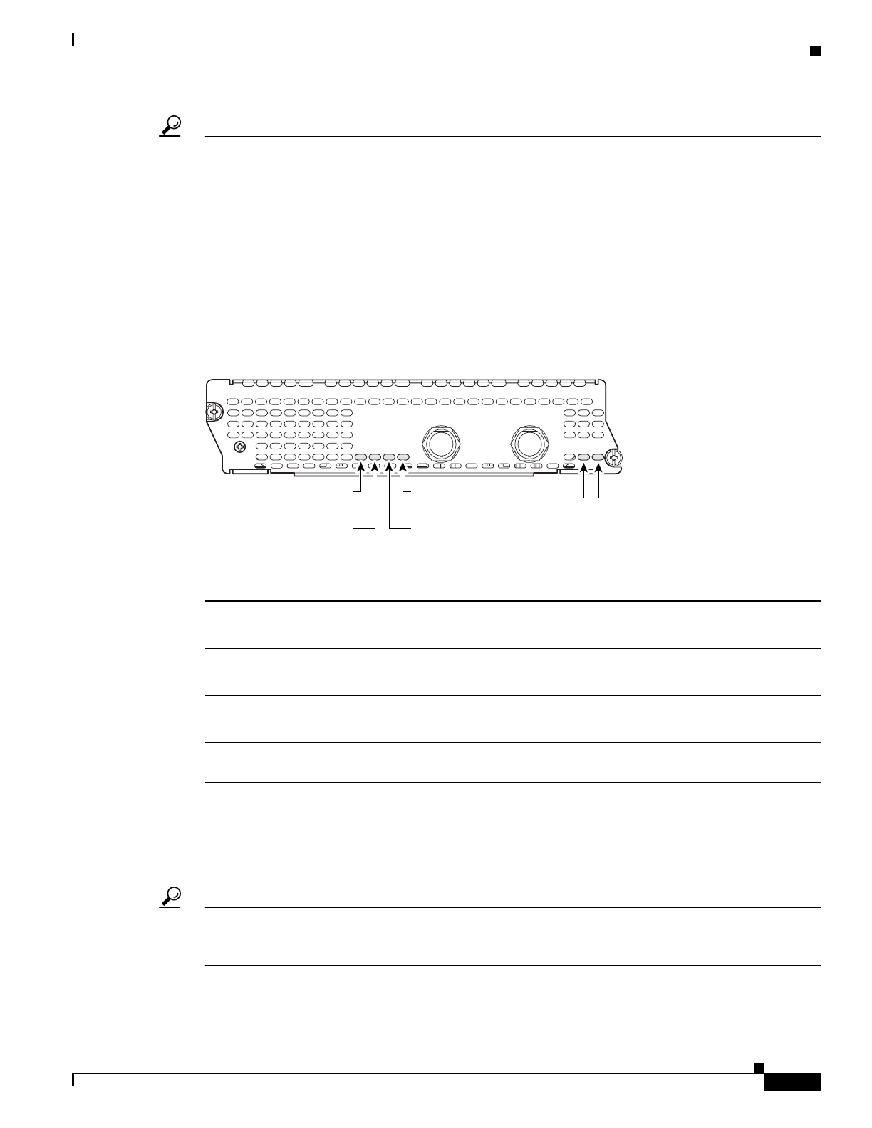
All network modules have an enable (EN) LED. This LED indicates that the module has passed its
self-tests and is available to the router. See Figure 20-3 and Table 20-1 for LEDs on the T3/E3 network
module.
Figure 20-3 T3/E3 LEDs
Related Documents
For additional information, see the following documents.
Tip For information on obtaining documentation, see the “Obtaining Documentation” section on page viii.
For information on obtaining technical assistance, see the “Obtaining Technical Assistance” section on
page xi.
Table 20-1 T3/E3 Network Module LEDs
LED Meaning
CD Green indicates that a signal is present on the port.
LP Yellow indicates that a loopback condition is present on the port.
AIS Yellow indicates an alarm on the DS3 transmission.
FERF/RAI Yellow indicates a remote failure at the far end of the connection.
AL Yellow indicates that the port is out of frame.
EN Green indicates that the network module has passed self-test and is available to
the router.
SEE MANUAL BEFORE INSTALLING NETWORK MODULE
72537
NM-1T3/E3
LP
AIS
AL
CD
TX
RX
FERF/RAI
T3/E3
EN
CD
LED
LP
LED
FERF/RAI
LED
AIS
LED
EN
LED
AL
LED