


Americas Headquarters
Cisco Systems, Inc.
170 West Tasman Drive
San Jose, CA 95134-1706
USA
http://www.cisco.com
Tel: 408 526-4000
800 553-NETS (6387)
Fax: 408 527-0883
Cisco, Cisco Systems, the Cisco logo, and the Cisco Systems logo are registered trademarks or
trademarks of Cisco Systems, Inc. and/or its affiliates in the United States and certain other
countries. All other trademarks mentioned in this document or Website are the property of their
respective owners. The use of the word partner does not imply a partnership relationship
between Cisco and any other company. (0705R)
© 2008 Cisco Systems, Inc. All rights reserved.
Printed in the USA on recycled paper containing 10% postconsumer waste.
78-18818-01
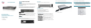
Typical Installation Scenario
The application diagram shown is an example of a typical network
configuration. This diagram shows the front panel of the SR216 and is used only
as a reference.
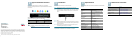
When you connect your network devices, make sure you don’t exceed the
maximum cabling distances, listed in the following table.
NOTE Use Category 5e Ethernet network cables for your Gigabit
connections.
From To Maximum Distance
Switch Switch 100 meters (328 feet)
Switch Computer 100 meters (328 feet)
2
Installation
Perform the steps in this section to install the hardware.
STEP 1 Make sure all the devices you will connect to the Switch are
powered off.
S
TEP 2 Connect a Category 5 Ethernet network cable to one of the numbered
ports on the Switch. Connect the other end to a PC or other network
device.
S
TEP 3 Repeat step 2 to connect additional devices.
S
TEP 4 Connect the supplied power cord to the Switch’s power port, and plug
the other end into an electrical outlet. When connecting power, always
use a surge protector.
S
TEP 5 Power on the devices connected to the Switch. Each active port’s
corresponding LED will light up on the Switch.
Congratulations! The installation of the 10/100 Switch is complete!
3
Specifications
The following table lists the specifications for the SR216 and SR224 10/100
Switches.
Model SR216 or SR224
Standards IEEE 802.3, 802.3u
Ports SR216: 16 10/100 Mbps RJ-45 ports
SR224: 24 10/100 Mbps RJ-45 ports
Cabling Type Cat5 Ethernet
LEDs SR216: System, 1 through 16
SR224: System, 1 through 24
Security Feature Security Slot
Dimensions WxHxD
11” x 1.75” x 9.45”
279 mm x 45 mm x 240 mm
Unit Weight 0.94 lbs (0.425 kg)
Power SR216: 3.3V/3A
SR224: 3.3V/5A
Certification FCC Class B, CE
Operating Temperature 32 to 104ºF (0 to 40ºC)
Storage Temperature -40 to 158ºF (-40 to 70ºC)
Operating Humidy 20% to 95%, noncondensing
Storage Humidy 5% to 90%, noncondensing
4
Where to Go From Here
Resource Location
Customer Support www.cisco.com/go/smallbiz
End User License Agreement www.cisco.com/go/smallbiz
Regulatory Compliance and Safety
Information
www.cisco.com/go/smallbiz
Warranty Information www.cisco.com/go/smallbiz
Cisco Partner Central site for Small
Business
www.cisco.com/web/partners/sell/
smb/
5