


9
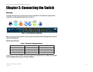
Chapter 3: Connecting the Switch
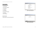
Placement Options
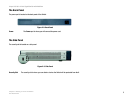
24-port 10/100 + 2-Port Gigabit Switch with WebView
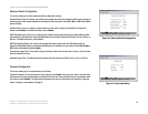
4. Repeat steps 2 and 3 to connect additional devices.
5. If you are using the Gigabit port, connect a Category 5e Ethernet network cable to the Gigabit port on the
Switch, and connect the other end to a Gigabit server or other network device.
6. If you are using the mini-GBIC port, then connect the mini-GBIC module to the mini-GBIC port. For detailed
instructions, refer to the module’s documentation.
7. Connect the supplied power cord to the Switch’s power port, and plug the other end into an electrical outlet.
8. Power on the devices connected to the Switch. Each active port’s corresponding LED will light up on the
Switch.
Placement Options
There are two ways to physically install the Switch, either set the Switch on its four rubber feet for desktop
placement or mount the Switch in a standard-sized, 19-inch high rack for rack-mount placement.
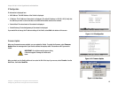
Desktop Placement
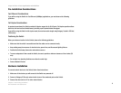
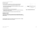
1. Attach the rubber feet to the recessed areas on the bottom of the Switch. See Figure 3-1.
2. Place the Switch on a desktop near an AC power source.
3. Keep enough ventilation space for the Switch and check the environmental restrictions mentioned in
specifications as you are placing the Switch.
4. Connect the Switch to network devices according to the Hardware Installation instructions, above.
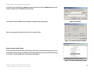
Figure 3-3: Attaching the Brackets to the Switch (Front
Panel Forward)
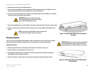
NOTE: If you need to reset the Switch, remove the power cord
from the back of the Switch and then reconnect it.
IMPORTANT: Make sure to use the power cord
that is supplied with the Switch. Use of a different
power cord could damage the Switch.
Figure 3-2: Attaching the Rubber Feet to the Bottom of
the Switch
IMPORTANT: Make sure to use the screws supplied with
the mounting brackets. Using incorrect screws could
damage the Switch and would invalidate your warranty.