


© 2012 Cisco and/or its affiliates. All rights reserved. This document is Cisco Public Information. Page 7 of 17
Use Case for the Cisco StackPower Feature
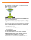
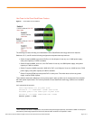
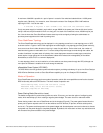
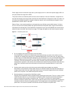
Figure 6. Power Stack of Four Switches
The following use cases will help you understand the Cisco StackPower technology and its main features.
Switches A, B, C, and D have the following configuration and power draw requirements
1
:
●
Switch A requires 946W to provide full PoE on all of its 48 ports. It has only one 1100W power supply;
extra power capacity of 154W is available.
●
Switch B requires 206W, since it is a non-PoE switch. It has only one 350W power supply; extra power
capacity of 144W is available.
●
Switch C requires 1646W to provide 1440W of full PoE+ on all 48 ports. It has one 1100W and one 715W
power supply; extra power capacity of 169W is available.
●
Switch D requires 576W to provide partial PoE on some ports. This switch does not have any power
supply, requires 576W of power.
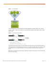
These switches have been cabled up to form a power stack in order to make use of unused power from switches
with lower power requirements. This is the key benefit of Cisco StackPower technology, flexible use of available
resources.
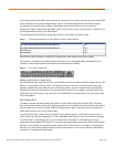
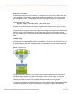
Let’s summarize the scenario:
Power requirements for the power stack
Switches A - D = 946W+206W + 1646W+ 576W =3374W
Available power in the common pool of power stack
Switches A - D= 1100W+ 350W+1100W+715W = 3265W
Deficit power = -109W
1
In this example, IOS release 12.2(53)SE2 is used, therefore the power budget required by each switch is 206W. In subsequent
IOS releases, power budget requirement values vary with the switch model and are reported in Table 1.