


2
Cisco uBR10012 Universal Broadband Router Fan Assembly Module
OL-5093-01
Scope
This document includes procedures for installing and removing the fan assembly module that comes with
the Cisco uBR10012 universal broadband router. This document also includes technical specifications
and troubleshooting information.
Contents
• Feature Overview, page 2
• Part Numbers and Technical Specifications, page 4
• Safety Warnings, page 5
• Removing and Replacing the Fan Assembly Module, page 9
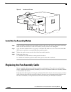
• Replacing the Fan Assembly Cable, page 11
• Troubleshooting the Fan Assembly, page 13
• Related Documentation, page 14
• Obtaining Documentation, page 14
• Obtaining Technical Assistance, page 16
• Obtaining Additional Publications and Information, page 17
Feature Overview
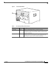
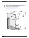
The Cisco uBR10012 universal broadband router uses a fan assembly module (Figure 1 on page 3)
containing four fans to supply cooling air to the chassis.
The fan assembly is located at the top of the chassis and is connected to the chassis with a blind mate
connector that plugs into a cable assembly and then into the chassis backplane.
Four internal fans draw cooling air into the front of the chassis and direct it across the internal
components to maintain an acceptable operating temperature. The air is exhausted through openings in
the rear of the chassis.
The fan assembly module works at variable speeds:
• Low speed (with a clean air filter): approximately 280 cubic feet per minute (cmf)
• High speed (with a clean air filter): approximately 450 cmf
The operating speed is determined by the fan assembly module. If the temperature at the fan’s outlet gets
to 40°C, then the blower starts to increase the speed of the fans. It does not reach high speed, however,
until the temperature at the outlet reaches 50°C.
Three LEDs (System OK, Single Fan Failure, and Multi-Fan Failure) located on the front of the fan
assembly indicate the status of the fans (see Table 1 on page 3).
Figure 1 on page 3 shows the fan assembly module.