


Step 1 Make sure that you are grounded using an
ESD-preventive wrist or ankle strap.
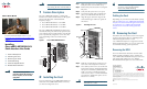
Step 2 Loosen the leadscrew (counterclockwise)
on the UCH until it is completely
disengaged from the faceplate.
Step 3 Pull the UCH straight away from the
faceplate using the leadscrew.
Caution Do not use the cables to pull the UCH
from the faceplate.
Figure 3 Loosening the Leadscrew
Removing the Card
Step 1 Using a T-10 TORX driver tool or flathead
screwdriver, unscrew the top and bottom
captive screws on the card.
Step 2 Simultaneously pivot both ejector levers
away from each other to disengage the
card from the backplane.
Caution The upconverter on the back side of the
card may be hot.
Step 3 Slide the card out of the slot and place it
on an antistatic surface with the
component side facing up.
Tip Always install a blank cover in an empty
slot to ensure proper cooling and airflow.
US0
US1
US2
US3
US4
US5
US6
US7
US8
US9
95233
4 Troubleshooting
Check the following:
1. Verify that the LEDs light and go through the
power on self test (POST) when the card is
inserted in the chassis.
2. Verify that the captive screws and ejector
levers are secure.
3. Verify that the POWER LED is on (green). If
the LED off (not green):
a. Verify that there is power to the system.
b. Verify that the card is configured for the
system.
4. If the card is cabled, check to see that the
cables are securely attached and in the correct
location.
5. Contact Cisco TAC for further information
and help at the following URL:
http://www.cisco.com/tac
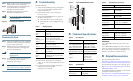
Table 1 LED Descriptions
LEDs Description
POWER
Green
Off
Power on
Power off
STATUS
Green
Blinking green
Yellow
Booted, passed diagnostics
Protect mode if redundant card
In bootup mode
MAINT
Off
Yellow
No action required
Okay to remove the card
US0–US19
Green
Off
Configured, able to pass traffic
Not enabled
DS0–DS4
Green
Off
Configured, able to pass traffic
Not enabled
Figure 4 Cisco uBR-MC5X20S/U/H LEDs
5 Technical Specifications
Table 2 Part Numbers
Description Part Num/Specification
Cisco uBR-MC5X20S
Cisco uBR-MC5X20U
Cisco uBR-MC5X20H
Blank card slot covers
UBR10-MC5X20S=
UBR10-MC5X20U=
UBR10-MC5X20H=
UBR10-MC-COVER=
Dual-Shielded Cable kit
Quad-Shielded Cable kit
CAB-RFSW520TPMF=
CAB-RFSW520QTPMF=
Universal cable holder:
UCH1
UCH2
Johnson Components:
133-8447-026
Cisco Systems:
CAB-520-UCH2
Table 3 Specifications
Ports Specification
Cisco uBR10-MC5X20S frequency range
Upstream
Downstream
5–42 MHz
70–860 MHz
95210
US0
US1
US2
US3
US4
US5
US6
US7
US8
US9
US10
US11
US12
US13
US14
US15
US16
US17
US18
US19
DS0
DS1
DS2
DS3
DS4
RF
RF
RF
RF
RF
uBR10-MC5x20U-D
POWER
STATUS
MAINT
POWER
STATUS
MAINT
US0
US1
US2
US3
US4
US5
US6
US7
US8
US9
DS0
DS1
DS2
DS3
DS4
RF
RF
RF
RF
RF
Standards
Cisco uBR10-MC5X20S—ITU J.112, ITU J.83,
Annex B
Cisco uBR10-MC5X20U/H—TU J.112, ITU J.83,
Annex A, Annex B. This card is compatible with
most cable systems worldwide, including but not
limited to Asia, Europe, and the Americas.
6 Related Documentation
For safety information, refer to:
Regulatory Compliance and Safety Information for
the Cisco uBR10012 Universal Broadband Router
For information about the 1-year warranty, go to:
http://www.cisco.com/en/US/docs/general/warrant
y/English/1Y1DEN__.html
For additional hardware installation and software
configuration information, go to:
http://www.cisco.com/en/US/products/hw/cable/ps
2209/tsd_products_support_series_home.html
Cisco uBR10-MC5X20U frequency range
Upstream
Downstream
5–65 MHz
70–860 MHz
Cisco uBR10-MC5X20H frequency range
Upstream
Downstream
5–65 MHz
70–860 MHz
Modulation
Upstream
(US0–US19)
QPSK
8–, 16–, 32–, 64–QAM
Downstream
(DS0–DS4)
64–QAM, 256–QAM
RF output power range—50 to 61 dBmV
Power consumption
MC5X20S
MC5X20U
MC5X20H
185W (631.2 BTU/hr)
175W (597.1 BTU/hr)
185W (631.2 BTU/hr)
Weight
16 lbs (7.26 kg)
Table 3 Specifications (continued)
Ports Specification