


Step 3 Connect the US cables to the US ports on
the card (US0–US7). All US ports are light
blue.
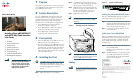
Figure 3 Inserting an Attenuator
5 Removing the Card
To prevent the alarms from activating,
administratively shut down the card using the
shutdown command in interface configuration
mode before removing it from the chassis.
Step 1 Make sure that you are properly
grounded.
Step 2 Disconnect all the cables from the cable
interface line card.
Step 3 Unscrew the captive installation screws on
the faceplate.
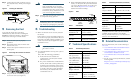
Figure 4 Removing the Card from the Chassis
Step 4 Grasp the handle and carefully pull the
card out of its slot (see Figure 4).
+42 dBmV
US2
US4
US5
US6
US7
ENABLED
DS0-IF
DS1-IF
uBR - MC28X
US1
US0
US3
88993
Upconverter
Attenuator
Cable
Connector
88982
U
S
0
U
S
1
U
S
2
U
S
3
U
S
4
U
S
5
U
S
6
U
S
7
E
NA
B
LE
D
DS0-RF
DS1-RF
u
B
R
- M
C
2
8
U
Caution Always handle the card by the carrier
edges and handle; never touch the
cable interface line card’s components
or connector pins. For proper cooling
and airflow, always install a line card
cover in an empty line card slot.
Step 5 Place the card on an antistatic surface with
its components facing upward.
Note If the card is being returned to the factory,
immediately place it in a static shielding
bag and proper packaging for protection.
6 Troubleshooting
1. Make sure that the card is securely seated in
the chassis.
If the captive screws do not tighten all the way,
the card is not properly seated in the chassis or
backplane. Carefully pull the card halfway out
of the slot, reinsert it, and tighten the captive
installation screws.
Caution A partially seated line card can cause
the router to reboot.
2. Are all enabled LEDs on? If yes, the system is
operational.
If no, check the following possibilities:
a. If the card has been enabled and
configured for operations, the enabled
LED remains on.
b. If a port is enabled but its enabled LED is
still off, check if the card has pulled away
from the router. Reseat the card in its slot.
(Do not have to turn off the system power
to do this.} After the system reinitializes
the interfaces, the enabled LED on the
card should come on.
3. If the enabled LED remains off after the above
checks, it is likely that the system has detected
a processor hardware failure. Go to the Cisco
TAC website http://www.cisco.com/tac for
further information and help.
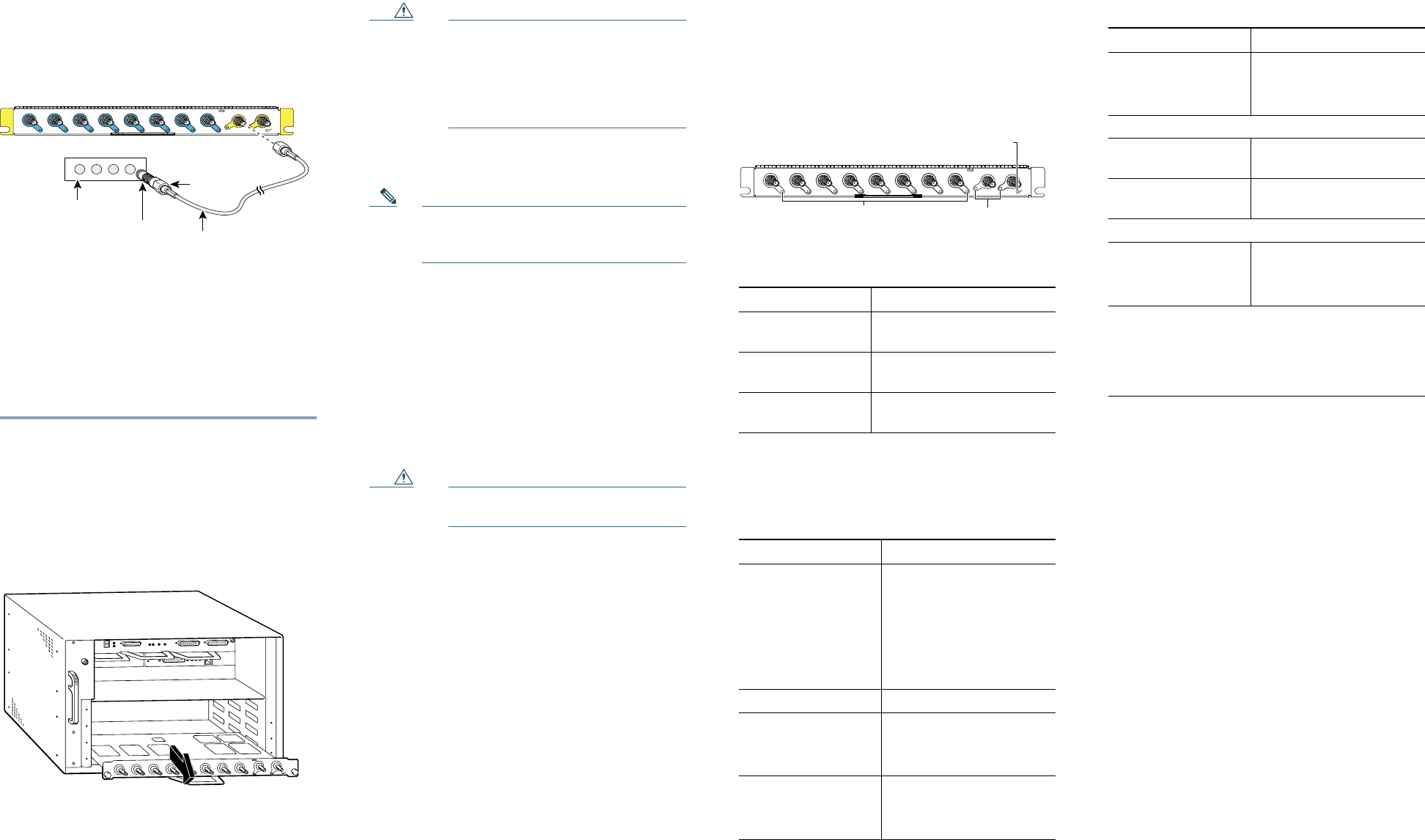
Figure 5 LEDs
7 Technical Specifications
Ta b l e 1 L E D s / S t a t u s
LED/Status Description
ENABLED—green
ENABLED—off
Card operating normally
Card not enabled
US—green
US—off
Upstream enabled
Upstream not enabled
DS—green
DS—off
Downstream enabled
Downstream not enabled
Ta b le 2 Te ch n ic al S pe c if i ca t io n s
Description Order Num/ Specifications
Cisco uBR-MC28U,
with upconverter
Cisco uBR-MC28X,
without upconverter
Cisco uBR-E-28U,
with upconverter
UBR-MC28U,
UBR-MC28U=
UBR-MC28X,
UBR-MC28X=
UBR-E-28U
UBR-E-28U=
Blank covers UBR-MC-COVER=
Weight—MC28U/E-
28U
Weight—MC28X
6 lbs (2.72 kg)
4.75 lbs (2.15 kg)
Power consumption
MC28U/E-28U
MC28X
80 Watts (273 BTU/h)
50 Watts (170.6 BTU/h)
88985
US2
US4
US5
US6
US7
ENABLED
D
S
0
-R
F
D
S
1
-R
F
uBR - MC28U
US1
US0
US3
Downstream
LEDs
DS0-DS1
Upstream
LEDs
US0-US7
Enabled
LED
8 Related Documentation
For more information, refer to the following at
Cisco.com:
• Cisco uBR7200 Universal Broadband Series
Hardware Installation Guide
• Cisco uBR7200 Series Cable Interface Line
Card Hardware Installation Guide
• Cisco uBR7200 Series Universal Broadband
Routers
• For the 1–year warranty information, visit the
following URL:
http://www.cisco.com/en/US/products/prod_w
arranties_listing.html
Output—MC28U/E-
28U
Output—MC28X
+50 to 61 dBmV at RF
+42 dBmV at IF (+/-2 dB)
Modulation
Upstream (US0–US7) QPSK 8–, 16–, 32–,
64–QAM
Downstream
(DS0–DS1)
64–QAM, 256–QAM
RF output power range—50 to 61 dBmV
Frequency range
Upstream
Downstream
5–65 MHz
70–860 MHz
The Cisco uBR-MC28U/X/E-28U line card is
compatible with most cable systems worldwide,
including but not limited to—Asia Pacific,
Europe, and the Americas. See Cisco IOS release
notes for more information.
Table 2 Technical Specifications (continued)
Description Order Num/ Specifications