


1-4
Cisco UCS C24 Server Installation and Service Guide
OL-26647-01
Chapter 1 Overview
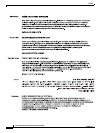
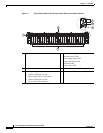
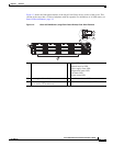
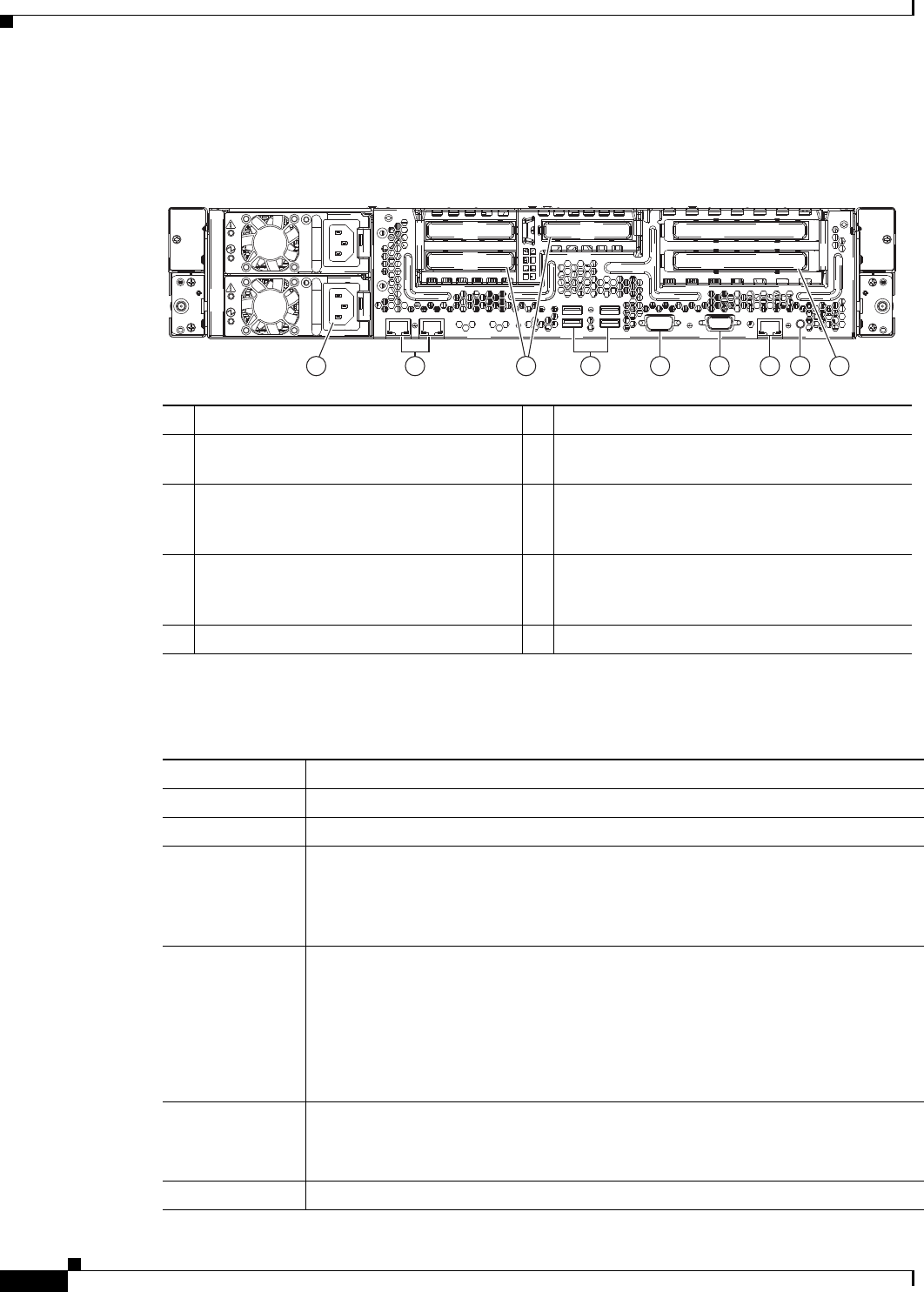
Figure 1-3 shows the rear panel features of the server (identical for all versions of the server). For
definitions of all LED states, see Status LEDs and Buttons, page 3-2.
Figure 1-3 Cisco UCS C24 Server Rear Panel Features
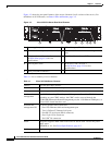
Table 1-1 lists a summary of server features.
.
1 Power supplies (two) 6 VGA video port (DB-15 connector)
2 Dual 1 Gb Ethernet ports (LAN1, LAN2) 7 10/100/1000 Ethernet dedicated management
port
3 PCIe slots 3, 4, and 5 on riser 2
See PCIe Slots, page 3-34 for slot
specifications.
8 Rear Identification button/LED
4 USB 2.0 ports (four) 9 PCIe slots 1 and 2 on riser 1
See PCIe Slots, page 3-34 for slot
specifications.
5 Serial port (DB-9 connector) –
PSU 2
PSU 2
PSU 2
PCIe 4
PCIe 4
PCIe 4
PCIe 3
PCIe 3
PCIe 3 PCIe 1
PCIe 1
PCIe 1
PCIe 2
PCIe 2
PCIe 2
PCIe 5
PCIe 5
PCIe 5
PSU 1
PSU 1
PSU 1
1 32 4 5 6 7 8 9
343735
Ta b l e 1-1 Cisco UCS C24 Server Features
Chassis Two rack-unit (2RU) chassis.
Processors Two Intel Xeon E5-2400 Series processors.
Memory The server provides 12 DIMM
1
sockets on the motherboard.
Baseboard
management
Pilot III BMC, running Cisco Integrated Management Controller (CIMC) firmware.
Depending on your CIMC settings, the CIMC can be accessed through the
10/100/1000 Ethernet dedicated management port, the 1-Gb Ethernet LOM ports, or
a Cisco P81E virtual interface card.
Network and
management I/O
The server provides these connectors:
• One 1-Gb Ethernet dedicated management port
• Two 1-Gb Base-T Ethernet LAN ports
• One RS-232 serial port (DB-9 connector)
• One 15-pin VGA
2
connector
• Six USB
3
2.0 connectors
Power Two power supplies: Both either 450 W each or 650 W each. Do not mix power
supply types.
Redundant as 1+1. See Power Specifications, page A-2.
Cooling Four hot-swappable fan modules for front-to-rear cooling.