


9
Installing the Cisco WAE Inline Network Adapter
OL-12480-03
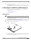
Installing Adapters in the FE-511, WAE-511, and WAE-611 Appliances
Installing an Inline Network Adapter
Before you install an adapter, review the following information:
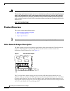
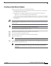
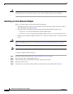
• The adapter slots are on the riser card assembly. You must first remove the riser card assembly to
access the adapter slots. (See Figure 4.)
• The appliance has two Peripheral Component Interconnect-Extended (PCI-X) adapter slots:
–
PCI-X slot 1 is for one full-height three-quarter-length adapter.
–
PCI-X slot 2 is for one low-profile half-length adapter; however, it is not used in this appliance.
• You must install the inline network adapter in PCI-X slot 1. (This slot is labeled “PCI 1” on the back
of the appliance.)
Caution When you handle static-sensitive adapters and appliances, take precautions to avoid damage from static
electricity. For details on handling these devices, see the “Protecting Against Electrostatic Discharge”
section on page 7.
Note The illustrations in this document might differ slightly from your hardware.
To install an inline network adapter, follow these steps:
Step 1 Review the safety information in the “Safety Guidelines” section on page 5.
Step 2 Power down the appliance and peripheral devices.
Step 3 Disconnect the power cord and then all external cables from the appliance.
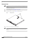
Step 4 Remove the appliance cover.
Note You may find it easier to route the cables before you install the adapter.
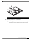
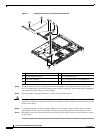
Step 5 Loosen the captive screw (labeled 3 in Figure 4) located on the rear of the appliance adjacent to PCI-X
slot 1 and remove the expansion slot cover.
Note You must install PCI expansion slot covers on all vacant slots so that you can maintain the
electronic emissions characteristics of the appliance and ensure proper cooling of internal
components.