


RJ-45 Port Connector and Cabling Specifications
26
Cisco Communication Media Module for Catalyst 6500 Series Switch and Cisco 7600 Series Router Installation and Verification Note
Warning
Hazardous network voltages are present in WAN ports regardless of whether power to the unit is OFF
or ON. To avoid electric shock, use caution when working near WAN ports. When detaching cables,
detach the end away from the unit first.
Statement 1026
Warning
To avoid electric shock, do not connect safety extra-low voltage (SELV) circuits to telephone-network
voltage (TNV) circuits. LAN ports contain SELV circuits, and WAN ports contain TNV circuits. Some
LAN and WAN ports both use RJ-45 connectors. Use caution when connecting cables.
Statement 1021
Warning
To reduce the risk of fire, use only No. 26 AWG or larger telecommunication line cord.
Statement 1023
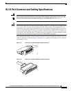
The T1 and E1 port adapter RJ-45 port connector and cabling specifications are described in this section:
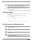
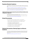
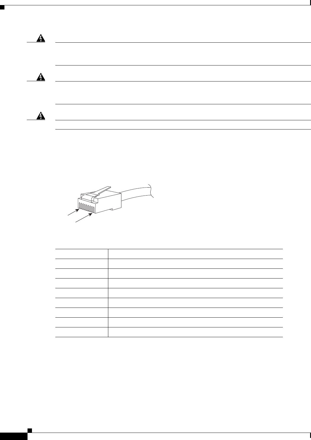
• Figure 14 shows the RJ-45 port cable connector pin orientation.
• Table 6 describes the RJ-45 port pinouts.
Figure 14 RJ-45 Port Connector
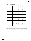
Table 6 6-Port T1 and E1 Port Adapter RJ-45 Port Pinouts
Pin
1
1. Table 6 lists the pinouts for the RJ-45 port connector, not the pinouts of the cable connecting to the port.
Description
1 Receive R1
2 Receive T1
3 Not connected
4 Transmit R
5 Transmit T
6 Not connected
7 Not connected
8 Not connected
192661
Pin 1
Pin 8
RJ-45 (both ends)