


14
Catalyst 6500 Series Switch Content Switching Module Installation Note
78-15751-03
Installing the CSM
Warning
Blank faceplates (filler panels) serve three important functions: they prevent exposure to hazardous
voltages and currents inside the chassis; they contain electromagnetic interference (EMI) that might
disrupt other equipment; and they direct the flow of cooling air through the chassis. Do not operate
the system unless all cards and faceplates are in place.
Installing a Module
This section describes how to install a supervisor engine or module in the Catalyst 6500 series switches.
Caution To prevent ESD damage, handle modules by the carrier edges only.
Caution During this procedure, wear grounding wrist straps to avoid ESD damage to the module. Do not directly
touch the backplane with your hand or any metal tool, or you could shock yourself.
Warning
Invisible laser radiation may be emitted from disconnected fibers or connectors. Do not stare into
beams or view directly with optical instruments.
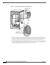
To install a supervisor engine or module in the chassis, perform these steps:
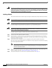
Step 1 Choose a slot for the supervisor engine or module.
Step 2 Verify that there is enough clearance to accommodate any interface equipment that you will connect
directly to the supervisor engine or module ports. If possible, place modules between empty slots that
contain only module filler plates.
Step 3 Verify that the captive installation screws are tightened on all modules installed in the chassis.
This action ensures that the EMI gaskets on all modules are fully compressed to maximize the opening
space for the replacement module.
Note If the captive installation screws are loose, the EMI gaskets on the installed modules will push
adjacent modules toward the open slot, reducing the opening size and making it difficult to
install the replacement module.
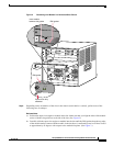
Step 4 Remove the module filler plate by removing the two Phillips pan-head screws from the filler plate. (To
remove a module, refer to the “Removing the Module” section on page 13.)
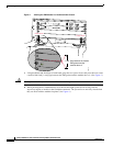
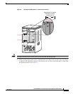
Step 5 Fully open both ejector levers on the new or replacement module. (See Figure 2.)