


14
Catalyst 6500 Series 24-Port FXS Analog Interface Module Installation Note
78-10975-02
Installing the 24-Port FXS Analog Interface Module
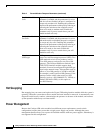
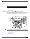
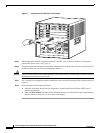
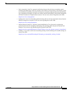
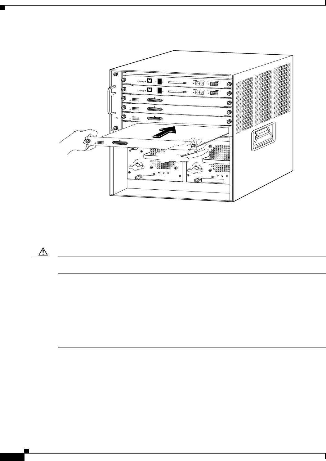
Figure 4 Installing the FXS Module in the Chassis
Step 5
While keeping the module oriented horizontally, carefully slide it into the slot until its front panel
contacts the ejector levers (see Figure 3).
Step 6 Using the thumb and forefinger of each hand, simultaneously push the left lever and the right lever in to
seat the module all the way into the backplane connector.
Caution Always use the ejector levers when installing or removing modules. A module that is partially seated in
the backplane causes the system to halt.
Step 7 Use a screwdriver to tighten the captive installation screws on the left and right sides of the module (see
Figure 3).
Step 8 Check the status of the module as follows:
a. After the module has booted and run diagnostics, ensure that the module Status LED is green
(module operational).
b. Enter the show module command at the Cat6000> prompt to verify that the system acknowledges
the new module and reports it as ok in the screen display.
38860
INPUT
OK
FAN
OK
OUTPUT
FAIL
o
INPUT
OK
FAN
OK
OUTPUT
FAIL
o
1
2
3
4
5
6
SUPERVISOR I
WS-X6K-SUP1
STATUS
SYSTEM
ACTIVE
PWR MGMT
RESET
CONSOLE
Switch Load
100%
1%
DTE/
DCE
PCMCIA
EJECT
PORT 1
LINK
PORT 2
LINK
SUPERVISOR I
WS-X6K-SUP1
STATUS
SYSTEM
ACTIVE
PWR MGMT
RESET
CONSOLE
Switch Load
100%
1%
DTE/
DCE
PCMCIA
EJECT
PORT 1
LINK
PORT 2
LINK
WS-X6624-FXS
24 PORT FXS ANALOG STATION
1
4
7
10
13
16
19
22
2
5
8
11
14
17
20
23
3
6
9
12
15
18
21
24
24-1
STATUS
WS-X6624-FXS
24 PORT FXS ANALOG S
TATION
1
4
7
10
13
16
19
22
2
5
8
11
14
17
20
23
3
6
9
12
15
18
21
24
24-1
STATUS
WS-X6624-FXS
24 PORT FXS ANALOG STATION
1
4
7
10
13
16
19
22
2
5
8
11
14
17
20
23
3
6
9
12
15
18
21
24
24-1
STATUS
WS-X6624-FXS
24 PORT FXS ANALOG STATION
1
4
7
10
13
16
19
22
2
5
8
11
14
17
20
23
3
6
9
12
15
18
21
24
24-1
STATUS