


Configuring Serial Interfaces on Cisco IOS XR Software
Information About Serial Interfaces
HC-119
Cisco IOS XR Interface and Hardware Component Configuration Guide
Default Settings for Serial Interface Configurations
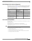
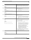
When an interface is enabled on a T3/E3 SPA, and no additional configuration commands are applied,
the default interface settings shown in Table 14 are present. These default settings can be changed by
configuration. Default settings do not appear in the output of the show running-config command.
Serial Interface Naming Notation
The naming notation for serial interfaces on a clear channel SPA is rack/slot/module/port, as shown in
the following example:
interface serial 0/0/1/2
The naming notation for T1, E1, and DS0 interfaces on a channelized SPA is
rack/slot/module/port/t1-num:channel-group-number, as shown in the following example:
interface serial 0/0/1/2/4:3.
Note A slash between values is required as part of the notation.
The naming notation syntax for serial interfaces is as follows:
• rack: Chassis number of the rack.
• slot: Physical slot number of the modular services card or line card.
• module: Module number. Shared port adapters (SPAs) are referenced by their subslot number.
• port: Physical port number of the T3 controller.
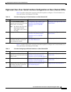
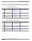
Table 14 Serial Interface Default Settings
Parameter Configuration File Entry Default Settings
Keepalive keepalive [disable]
no keepalive
keepalive 10 seconds
Encapsulation encapsulation [hdlc | ppp] hdlc
Maximum transmission unit (MTU) mtu bytes 4474 bytes
Cyclic redundancy check (CRC) crc [16 | 32] 32
Data stream inversion on a serial
interface
invert Data stream is not inverted
Payload scrambling (encryption) scramble Scrambling is disabled.
Number of High-Level Data Link
Control (HDLC) flag sequences to be
inserted between the packets
transmit-delay Default is 0 (disabled).