


5
Testing
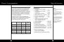
Test Load Power Minimum Cable Size
100 w #16 AWG copper
250 w #12 AWG copper
500 w # 8 AWG copper
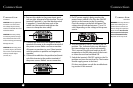
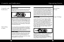
The end of the cable that connects to the invert-
er must have its insulation stripped off for about
1/2 inch (1.25cm) back from the end,exposing
the bare copper.
The other end of the cable,which connects to
the power source,must be terminated with a lug
or other connector that provides a secure,low
resistance connection.
For example,if the power source is a battery, the
cable must be terminated with a battery terminal
that clamps to the post on the battery.
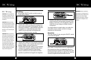
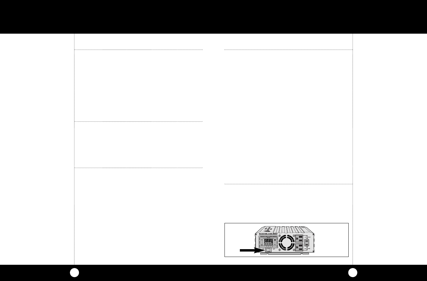
Connection
1. Turn the ON/OFF switch on the inverter to
the OFF position.
If the power source is a DC power supply,
switch it off as well.
Testing/Connection
4
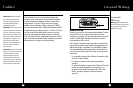
Quick Checkout
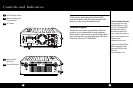
This section provides you with basic information
about the inverter and how to check its perfor-
mance before installation.Be sure to have the fol-
lowing on hand:
•
A 12 volt DC power source (such as a vehicle battery)
•
A set of cables to connect the power source to the inverter
•
A test load that can be plugged into the AC receptacle
on the inverter
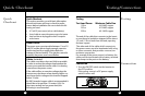
Power Source
The power source must provide between 11 and 15
volts DC and be able to supply enough current to
run the test load.As a rough guide,divide the
wattage of the test load by 10 to get the current (in
amperes) the power source must deliver.
Cables (included)
The cables must be as short and thick as possible
in order to reduce the voltage drop between the
power source and the inverter when it is drawing
current from the power source.
If the cable suffers an excessive voltage drop,the
inverter may shut down when drawing higher cur-
rents because the voltage at the inverter dropped
below 10 volts.
#4 AWG stranded copper cable is recommended.It
should be no longer than 1.5 meters (4 ft.).For
short term testing at a low power level,the
following is recommended:
Quick
Checkout
Quick Checkout
Testing
Connection