Chapter 3: Setting up the Printer16
A798 Thermal Receipt Printer: User Guide A798-UG00001 Rev. A 10/07 10/07 A798-UG00001 Rev. A A798 Thermal Receipt Printer: User Guide
A798 Thermal Receipt Printer: User Guide A798-UG00001 Rev. A 10/07 10/07 A798-UG00001 Rev. A A798 Thermal Receipt Printer: User Guide
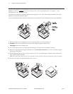
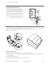
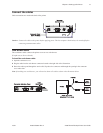
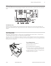
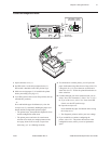
To install the communication cable:
1 Make sure the host computer is off.
2 Open the connector cover at the rear of the printer.
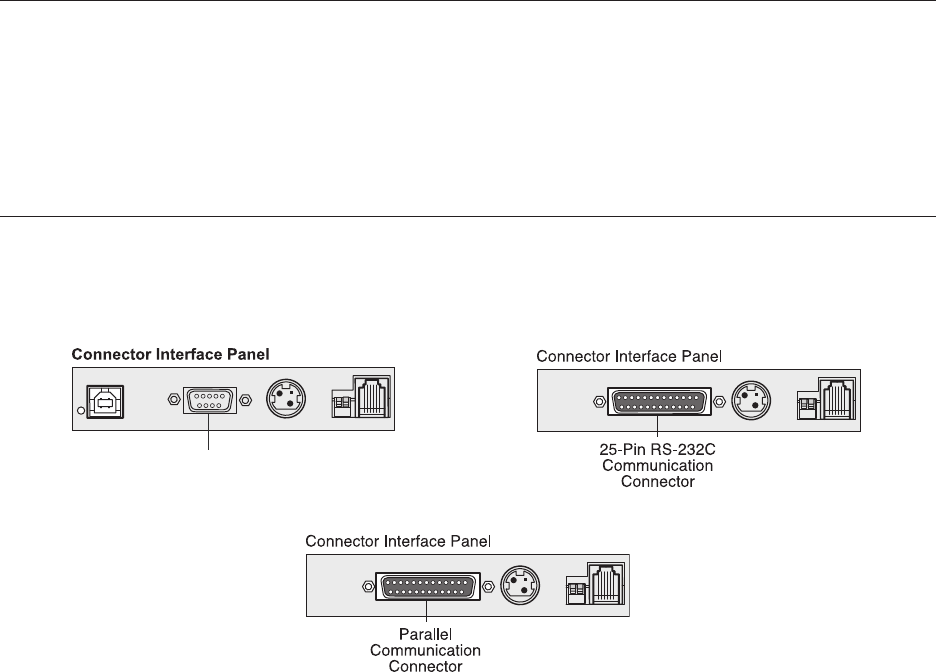
3 Attach the communication cable to the communication connector, shown in the center in the illustration. Tighten the
screws to secure the cable and ensure a stable connection.
4 Connect the cable to the host computer.
Communication cables
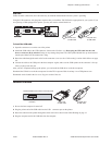
According to your printer configuration, the printer has different communication connection options. Select and attach
either 9-pin RS-232C, 25-pin RS-232C, standard USB, or powered USB communication cable to the printer and host
computer.
For printers with both 9-pin RS-232C and USB connectors, only a single communication connection is to be used during
operations.
RS-232C cable (9-pin and 25-pin) and Parallel
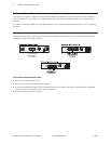
The communication cable connects the printer to the host computer using either the 9-pin or 25-pin RS-232C interface.
Installation is identical for both connectors.
9-pin RS-232C
communication
connector
25-pin RS-232C
communication
connector


