


5–48 Maintenance and Service Guide
Removal and Replacement Procedures
5.15 System Board
✎
When replacing the system board, ensure that the following
components are removed from the defective system board and
installed on the replacement system board:
■ Memory modules (Section 5.6)
■ Mini PCI communications module (Section 5.7)
■ RTC battery (Section 5.8)
■ Power connector cable (Section 5.15)
■ Heat sink (Section 5.18)
■ Processor (Section 5.19)
■ Fan assembly (Section 5.20)
■ Fan assembly (Section 5.20)
■ PC Card assembly (Section 5.21)
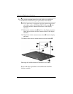
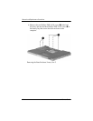
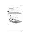
1. Prepare the computer for disassembly (Section 5.3),
and then remove the following components:
a. Hard drive (Section 5.4)
b. Memory/Mini PCI module compartment cover
(Section 5.6)
c. Optical drive (Section 5.9)
d. Switch cover (Section 5.10)
e. Keyboard (Section 5.11)
f. Display assembly (Section 5.12)
g. Base enclosure (Section 5.13)
System Board Spare Part Number Information
For use with defeatured models
For use with full-featured models
430150-001
430151-001