


— 11 —
P75
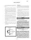
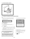
Convergence Fine Adjustment
Set DY four-pole magnet to mechanical center
before adjustment.
This should be prime mode.
1. Receive R.B. cross-hatch.
2 Adjust H.STAT and V.STAT at four-pole magnet.
4 Pole Magnet
SECTION 4
ADJUSTMENTS
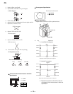
Landing Rough Adjustment
1. Enter the full white signal.
2. Adjust the contrast to the maximum.
3. Input full green signal.
4. Moving the DY backward, and adjust coarsely the purity
magnet sothat a green raster positions in the center of
screen.
5. Moving the DY forward, adjust so that an entire screen
becomes pure green.
6. Adjust the tilt of DY, and tighten lightly with a clamp.
• Landing Fine Adjustment
1. Place the set in the Helmholtz coil.
2. Enter a green signal only.
3. Degauss the entire screen with hand-degausser. Then auto-
degauss it.
4. Attach a wobbling coil to the specified position of CRT
neck.
5. Attach a landing adjuster sensor on the CRT.
6. Using a landing checker, adjust the DY position, purity,
tilt of DY.
7. Clamp the DY screw.
Clamping torque: 22
+ 2 kgcm (2.2+ 0.2 N.m)
• Convergence Rough Adjustment
1. All digital convergence data should be zero by MCP.
2. Enter the white crosshatch signal.
3. Adjust roughly the horizontal and vertical
convergence at four-pole magnet.
4. Adjust roughly HMC and VMC at six-pole
magnet.
*The parts above ( ~ ) are necessary for DAS adjustment.
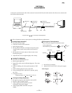
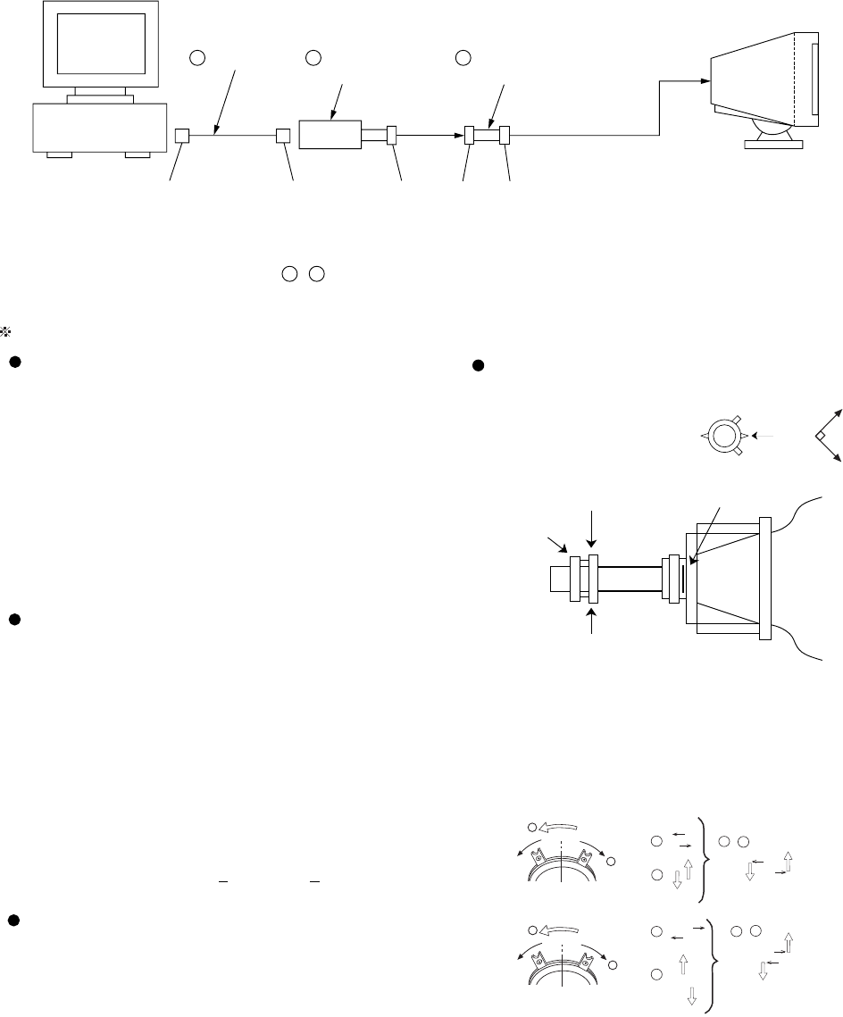
IBM AT Computer
as a Jig
1-690-391-21
1
A-1500-819-A
Interface Unit
2
3
D-sub
(9 Pin [female])
mini Din
(8Pin)
4 Pin
3-702-691-01
Connector Attachment
3
To BUS CONNECTOR
4 Pin 4 Pin
1
2
1
R
B
R
B
R
B
R
B
1
2
R
B
R
B
2
1
2
1
+
2
1
+
2
1
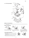
Set the
finger
Mechanical
Center
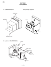
NECK Assy
6-pole Mg
P.S Mg
XBV
DY CRT
4-pole Mg
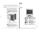
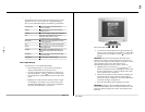
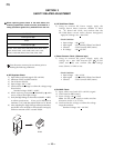
Connect the communication cable of the connector located on the D board on the monitor. Run the service software and
then follow the instructions.
Allow a 30 minute warm-up period prior to making the following adjustments:
P.S Mg