


Hardware
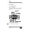
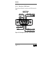
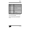
Connector
Version 1.03
3-9
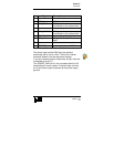
Pin Signal Description
1 Uni_Out2 Connected to Port 6.7
2 CAN_L CAN_L bus line (dominant low)
3 CAN_GND CAN ground
(connected on the cable shield)
4 Uni_Out0 Connected to Port 6.5 or UART
Rx or CAN2 RX
0
5 CAN_SHIELD CAN ground
(connected on the cable shield)
6 POWER_GND power supply input ground
7 CAN_H CAN_H bus line (dominant
high)
8 Uni_Out1 Connected to Port 6.6 or UART
Tx or CAN2 TX
0
9 POWER_V+ power supply input +7..32V
Pin 1, 4 and 8 are used to provide the additional signals
for the second CAN channel or the UART. In standard
version the inputs are protected.
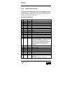
Port 6.5, Port 6.6 and Port 6.7 are used as additional
signal line. In case of standard version the ports are
protected.