


PC-CARD-DIO48 User's Guide Installing the PC-CARD-DIO48
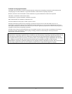
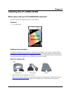
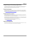
Figure 6
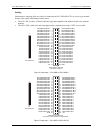
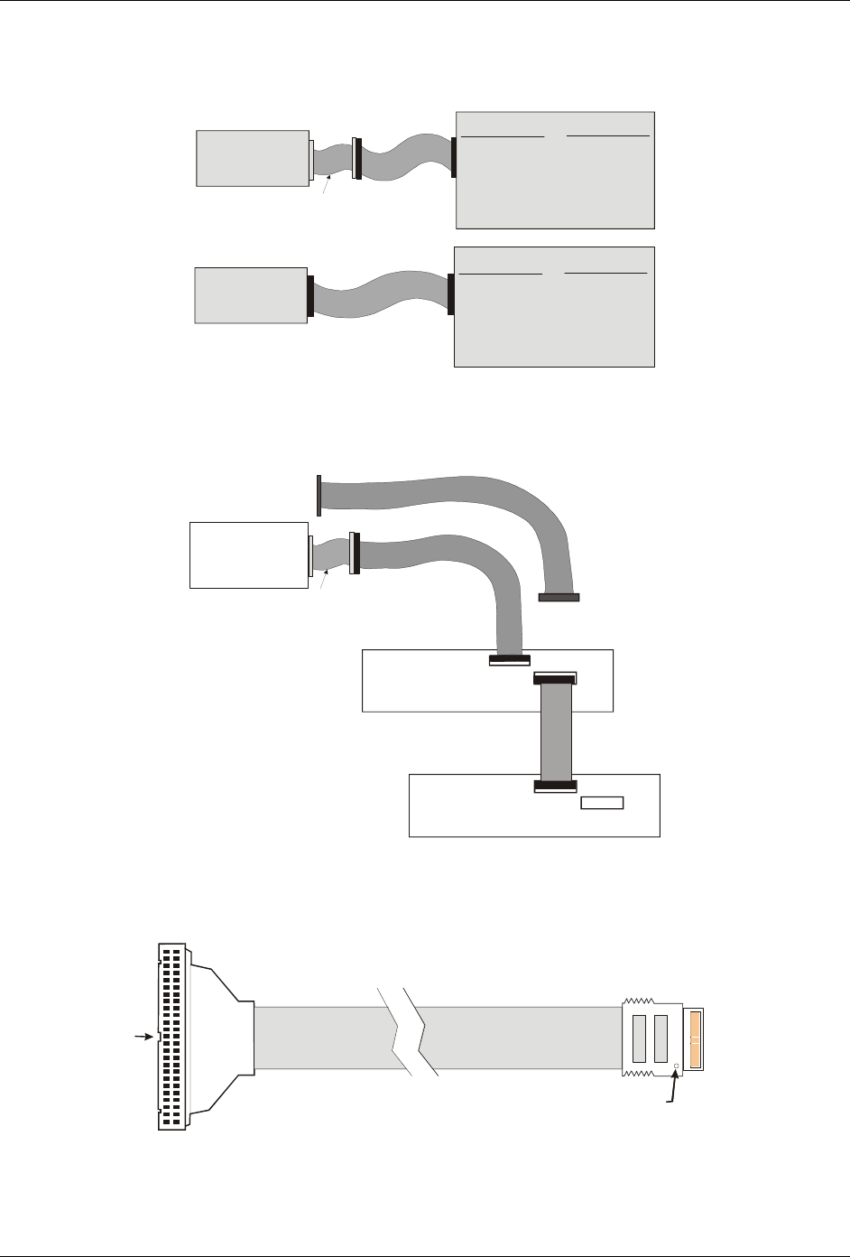
Figure 6. Connecting to screw terminal or relay boards
shows a map of the two methods of cabling the PC-CARD-DIO48 to various screw terminal or signal
conditioning boards.
C50FF-x
TERMINALS
CIO-MINI50
CIO-SPADE 50
CIO-TERM100
SCB-50
RELAYS
SSR-RACK24
CIO-ERB24
CIO-SERB24
PC-CARD-DIO48
CPCC-50M-4
CIO-ERB48
CIO-SERB48
TERMINALS
CIO-MINI50
CIO-SPADE 50
CIO-TERM100
SCB-50
RELAYS
PC-CARD-DIO48
CPCC-50F-39
or
SSR-RACK48
SSR-RACK24
CIO-ERB24
CIO-SERB24
CIO-ERB48
CIO-SERB48
SSR-RACK48
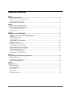
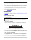
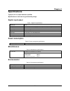
Figure 7
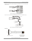
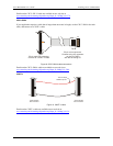
Figure 7. Cable map to the CIO-ERB24 or SSR-RACK24
shows how to connect the PC-CARD-DIO48 to two SSR-RACK24 or CIO-ERB24 relay racks.
CIO-ERB24
or
SSR-RACK24
CIO-ERB24
or
SSR-RACK24
PC-CARD-DIO48
In
In
Out
Out
C50FF-x
C50FF-#
CPCC-50M-4
CPCC-50F-39
Or
CPCC-50F-39
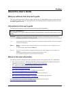
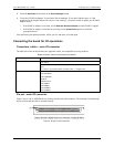
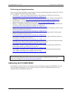
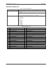
50-pin female IDC connector.
50
49
2
1
Dot
50-pin micro connector.
Connect to the I/O connector
on the PC-CARD
with the dot facing UP.
Key
50
1
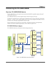
Figure 8. CPCC-50F-39 cable connections
13