


Removal and Replacement Procedures
Maintenance and Service Guide 5–59
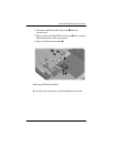
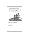
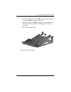
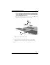
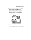
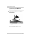
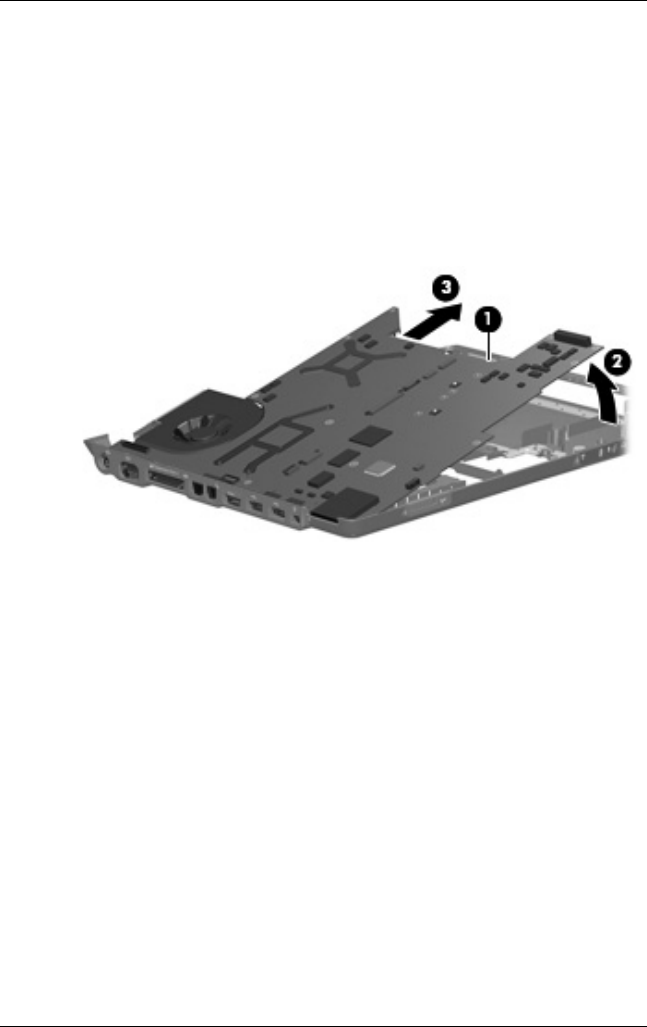
4. Use the optical drive connector 1 to lift the right side of the
system board 2 until it rests at an angle.
5. Slide the system board 3 to the right until the connectors on
the left side of the system board disengage from the base
enclosure.
6. Remove the system board.
Removing the System Board