


Chapter 4 - LED Patterns 13
Chapter 4 - LED Patterns
Some of the LEDs on the front of the VSR multigigabit switching router serve dual functions.
In addition to indicating certain router-wide operating conditions and they may also display
port-specific information.
v
Note: Any continuous flashing pattern not noted in this chapter may be caused by a hard-
ware failure. Please call Compatible Systems Technical Support if your router shows a hard-
ware failure.
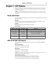
Router LED Patterns
The following LEDs and light patterns provide information about the VSR’s physical state and
operating conditions.
Over Temp
The router is above the proper operating temperature. The filter needs changing. See the
appropriate VSR chassis section of the manual for instructions.
Sys Ready
The router booted properly without detecting any failures.
General Indicators
HSSI-10/100 RIOP LED Patterns
The following LEDs and light patterns provide information about the HSSI-10/100 RIOP
interfaces.
Ethernet Traffic Indicators
Scan from 1 to 3: Ethernet transmit packet
Scan from 5 to 3: Ethernet receive packet
HSSI Indicators
Scan from 1 to 3: WAN transmit packet
Scan from 5 to 3: WAN receive packet
v
Note: The four lights on the HSSI card are for manufacturing diagnostic purposes only and
are off during normal operating conditions.
Ethernet Connection Indicators
Link: The Link light indicates that there is a good connection to the hub.
Activity: The Activity light indicates that there is activity across the link.
100: The 100 light indicates that the interface is operating at 100 Mbps.
Ethernet Lights HSSI Lights Indication
5 flashing 1 flashing Router stacks starting up.
3&4 flashing 2&3 flashing No OS loaded. Running from ROM.
1&4 flashing 2&5 flashing Erasing OS in Flash ROM.
5 flashing 1,2&3 flashing Erasing config in Flash ROM.
1 - 5 scanning 5 - 1 scanning Flash ROM erase due to switch setting five or six
is complete. Set switch to zero and cycle power.