


BlueStorm Installation Guide, Connect Tech Inc.
Revision 0.10 13
the operating system is booted by the current driver/software RS-485 mode. The jumper is used
to ensure that a port will power-on tri-stated. For example, the RS-485 mode selection in the
Windows control panel will override this jumper setting once a port is opened.
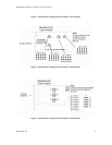
The BlueStorm/LP RS-422/485 uses JC to configure Auto-485 mode, while the BlueStorm/SP
Opto uses J1.
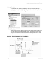
Note that on BlueStorm/LP RS-422/485 models the Auto 485 is a single
jumper. The second site is not in use. See Figure 1 for the location of this
jumper. On the BlueStom/SP Opto, the first position controls the first port pair,
while the second position controls the second port pair.
Power-On Tri-state (BlueStorm/SP Models Only, Excludes
BlueStorm/SP RJ-11)
BlueStorm/SP models offer a power-on tri-state similar to the Auto-485 mode listed above. The
BlueStorm/SP will tri-state a port configured as RS-485 full duplex or RS-485 multi-drop slave.
This is meant to ensure compatibility with our legacy Blue Heat/PCI cards for customers
upgrading to the newer BlueStorm family.
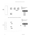
Jumper J1 controls the power-on tri-state functionality. Install a jumper on the first location of
the J1 in order to tri-state Port 1 at power-on, install a jumper on the second position of J1 to
control Port 2, etc. Ports will not come out of tri-state until the driver opens the associated port
and begins transmission.
Half Duplex and Multi-drop Slave modes require you to select the appropriate
mode via software. Please refer to the readme.txt files found in the appropriate
directories on the BlueStorm/LP/SP/SP Opto CD.
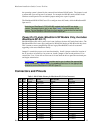
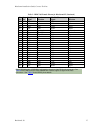
Connectors and Pinouts
Table 1: DB-25 Male Pinouts for BlueStorm/LP (2 Port Connector)
Pin
No.
Port
No.
RS-232
Signal
Signal
Direction
RS-422/485
Signal
Signal
Direction
1 2 SG signal gnd. SR signal ref.
2 1 TXD output TXD- output
3 1 RXD input TXD+ output
4 1 RTS output RTS- output
5 1 CTS input RTS+ output
6 1 DSR input CTS- input
7 1 SG signal gnd. SR signal ref.
8 1 DCD input RXD+ input
9 2 TXD output TXD- output
10 2 RXD input TXD+ output
11 2 RTS output RTS- output
12 2 CTS input RTS+ output
13 2 DSR input CTS- input
14 NC no connect NC no connect
15 NC no connect NC no connect
16 NC no connect NC no connect
17 NC no connect NC no connect
18 NC no connect NC no connect