


CANpro/104 User Manual
CTIM-00043 (0.01) 1/15/2010 www.connecttech.com 22
800-426-8979 | 519-836-1291
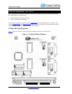
Other On-board Jumper Selection
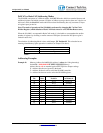
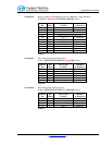
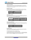
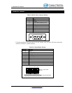
Near each I/O connector a 2x2 jumper block (either J4 or J5) will allow the configuration of both bus
termination and slew rate limiting for the transceiver. J4 configures options for CAN controller 0, while J5
configures options for CAN controller 1.
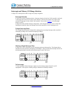
Installing a jumper on the first location of J4 or J5 (the gray area above) will enable a 120 Ohm termination
resistor across the CAN-H and CAN-L lines. Termination is recommended for improved signal integrity in
longer transmission lines. Termination requirements should be evaluated on a case by case basis. Typically
both ends of a CAN bus are terminated, but no termination is enabled on cards that sit in the middle of the
bus.
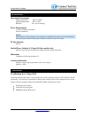
Installing a jumper on the second location of J4 or J5 (the gray area above) will disable slew rate limiting for
the associated CAN port. Slew rate limiting will reduce the emitted switching noise that is sent out onto the
CAN bus lines and radiated from those lines. Switching noise may cause EMI / EMC incompatibilities
depending on the cabling used to support the system. The use of slew rate limiting may aid in a system that is
close to the limit of emissions already. Properly shielded cabling will dramatically reduce emissions.
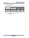
Slew rate limiting may only be used on busses operating at slower baud rates. With the jumper installed, full
1Mbps operation is possible.