


Power Options
Power Considerations
Voltage in the range of 10–36 VDC or 8–24 VAC must deliver current commensurate
with power consumption. Recommended size for solid power conductors is 16–22 AWG;
for stranded conductors, use 16–18 AWG. Common is directly connected to zero volts
and chassis is isolated from zero volts. Input connections are reverse-polarity protected.
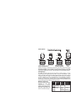
LED Indicators
The “PWR” LED glows solid green when the switch is properly powered. To aid in
troubleshooting, each copper port has two LEDs. The Port 1 LED labelled “L” glows
solid if a link exists, flashes to show activity and shows data rate by colour: green fo
r
100 Mbps and yellow for 10 Mbps. The LED labelled “D” glows solid green if full-duplex
is on or is unlit when the port is in half-duplex mode — but in half-duplex operation it
will flash if a collision occurs. The LEDs of Ports 2–6 are unlabeled but work the same.
The fibre port (7 and 8) LEDs glow solid green if linked to a working 100BASE-FX port
and each LED flashes when data moves through the port.
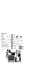
Network Connections
The switch employs Auto-MDIX
technology so that either
straight-through or crossover
cables can be used to connect to
network interface adapters or to
other hubs. Cable issues are
shown in the chart to the right
Full-Duplex :
2km(6562ft)
10BASE-T
100BASE-TX
10/100 Mbps
CAT 5 UTP
100BASE-FX
100 Mbps
Multimode
50/125 or
62.5/125 µm
100m(328ft)
Fibre
Medium
Signaling &
Data Rate
Mini
e
Needed
mum
Cabl
Maximum
Segment
Distance
Copper
Single Mode
Full-Duplex :
15 km (49212 ft)