


3
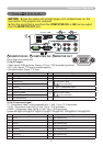
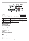
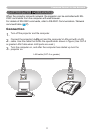
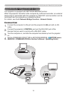
Connection to the ports
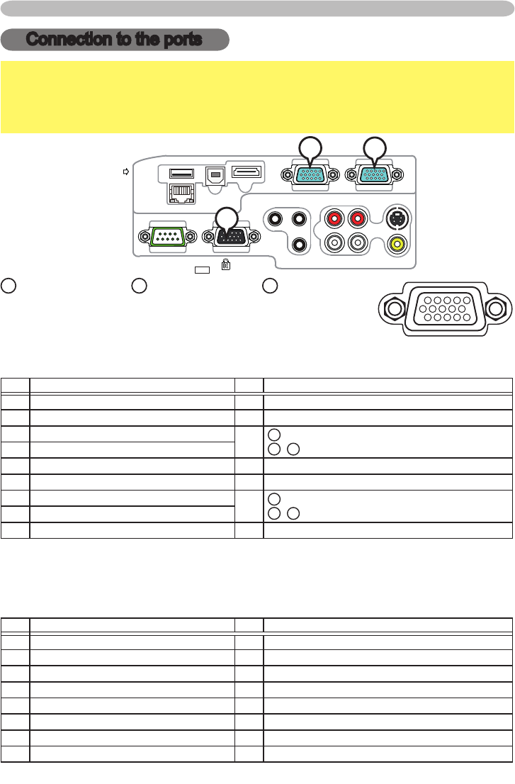
Connection to the ports
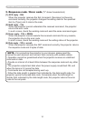
NOTICE
►Use the cables with straight plugs, not L-shaped ones, as the
input ports of the projector are recessed.
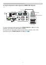
►Only the signal that is input from the COMPUTER IN1 or IN2 can be output
from the MONITOR OUT port.
COMPUTER IN1COMPUTER IN2
HDMI
USB TYPE B
S-VIDEO
VIDEO
AUDIO OUT
AUDIO IN3AUDIO IN1
AUDIO IN2
MIC
MONITOR OUT
CONTROL
USB
TYPE A
DC5V
0.5A
B
A
C
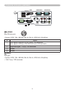
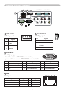
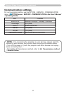
A
COMPUTER IN1,
B
COMPUTER IN2,
C
MONITOR OUT
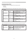
D-sub 15pin mini shrink jack
(1) for PC signal
• Video signal: RGB separate, Analog, 0.7Vp-p, 75Ω terminated (positive)
• H/V. sync. Signal: TTL level (positive/negative)
• Composite sync. Signal: TTL level
Pin Signal Pin Signal
1
Video Red 10 Ground
2 Video Green 11 (No connection)
3 Video Blue
12
A
: SDA (DDC data)
B
,
C
: (No connection)
4 (No connection)
5 Ground 13 H. sync / Composite sync.
6 Ground Red 14 V. sync.
7 Ground Green
15
A
: SCL (DDC clock)
B
,
C
: (No connection)
8 Ground Blue
9 (No connection) - -
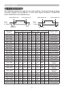
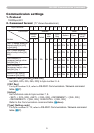
(2) for Component signal
• Y : Component video Y with composite sync, 1.0±0.1 Vp-p, 75 Ω terminator
• Cr/Pr : Component video Cr/Pr, 0.7±0.1 Vp-p, 75 Ω terminator
• Cb/Pb : Component video Cb/Pb, 0.7±0.1 Vp-p, 75 Ω terminator
System:480i@60,480p@60,576i@50,576p@50,720p@50/60,1080i@50/60,1080p@50/60
Pin Signal Pin Signal
1
Cr/Pr 9 (No connection)
2 Y 10 Ground
3 Cb/Pb 11 (No connection)
4 (No connection) 12 (No connection)
5 Ground 13 (No connection)
6 Ground Cr/Pr 14 (No connection)
7 Ground Y 15 (No connection)
8 Ground Cb/Pb - -