


Crestron CEN-CN Ethernet/Cresnet Interface
Operations Guide - DOC. 5721 Ethernet/Cresnet Interface: CEN-CN •• 7
Before installing any development tools, confirm that all other applications such as
Microsoft
®
Office, etc. are closed. The website and CD provide instructions for
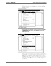
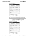
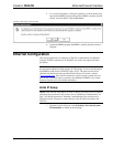
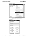
installing the various tools. When initiating a custom install from the CD, the user is
presented with a list of the software programs, documentation, and other resources.
For each item, set or clear a checkbox to the left of the item to direct the installation
program whether to install that component onto the hard drive. The size of the each
item installed determines how much disk space is required. Each development tool
contains a help file that can be opened from the Help pull-down menu. Refer to these
files for additional information.
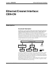
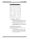
Obtaining Communications
To configure the CEN-CN, it is necessary to first obtain communication with the
device. Communication can be established via the CEN-CN rear panel PC port. To
perform the configuration of the CEN-CN, the provided 6-conductor modular cable
and an RJ11 to DB9F adapter (not supplied) are required. The adapter is available
commercially or contact Crestron customer service for part number 15556. If
obtained, proceed to “Hookup Diagram for Configuration” on page 7.
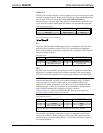
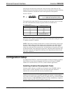
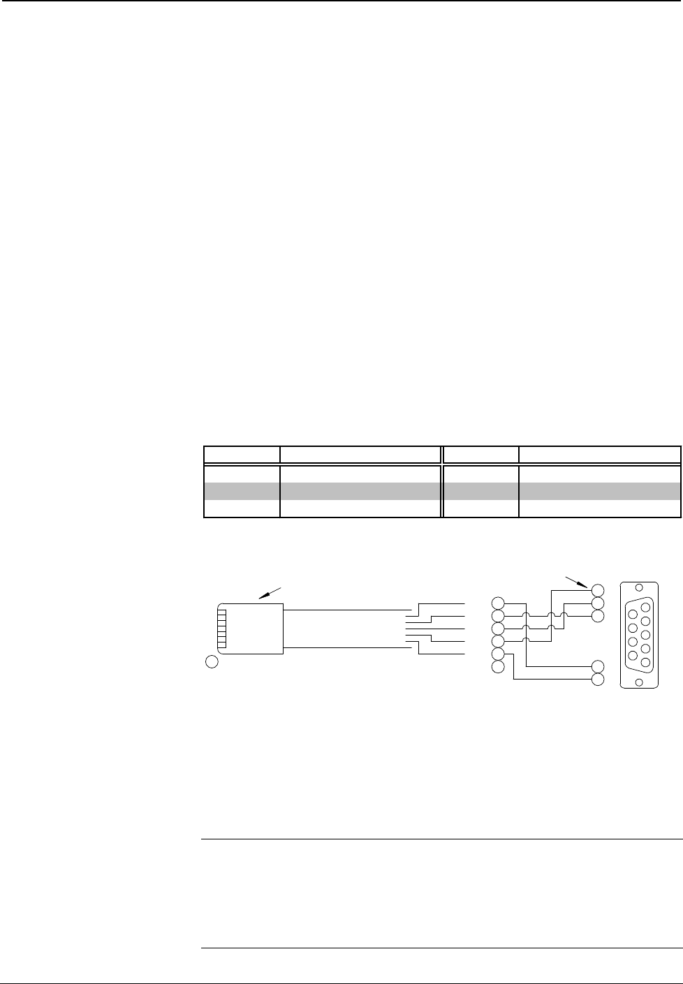
Configuration Cable Fabrication Specifications
In the event that an RJ11 to DB9F adapter is not available, the table and the diagram
below are provided so that the cable can be fabricated on site.
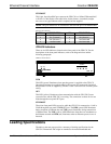
RJ11 Modular Cable Pinouts
PIN DESCRIPTION PIN DESCRIPTION
1 CTS (Clear to Send) 4 TxD (Transmitted Data)
2 GND 5 RTS (Request to Send)
3 RxD (Received Data) 6 Not Connected
CEN-CN to PC Cable Specification
1
2
3
4
5
6
7
8
9
8
7
5
3
2
6
5
4
3
2
1CTS
GND
RxD
TxD
RTS
n/c
TO PC
COM PORT
TO CEN-CN
PC PORT
1
PART #
AWC10152-A
PART #
748047-1
PART #
641337
REAR VIEW OF
CONNECTOR
(9-PIN FEMALE)
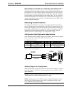
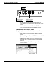
Hookup Diagram for Configuration
When performing the configuration, refer to the figure on the next page for a typical
connection diagram. Complete the following steps in the order provided to ensure
proper connection.
NOTE: If an RJ11 to DB9F adapter and/or modular cables are not available, refer to
“Configuration Cable Fabrication Specifications” on page 7.
NOTE: Operating power for the CEN-CN may be supplied either by the external
AC power pack (included) that provides 12VDC or supplied by 24VDC via the
4-wire CEN-CN Cresnet system wiring.