


50 Watt Cresnet Power Supply Crestron GLA-PWSI50
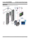
Physical Description
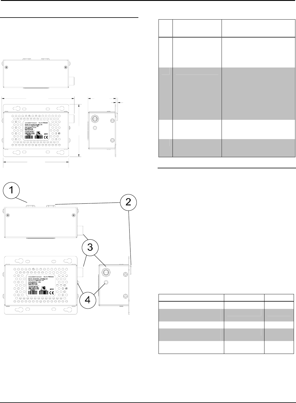
This section provides information on the connections,
controls and indicators available on the GLA-PWSI50.
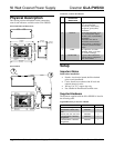
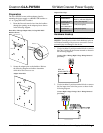
GLA-PWSI50 Overall Dimensions
0.31 cm
(0.12 in)
5.45 cm
(2.15 in)
12.77 cm)
(5.03 in)
10.16 cm
(4.00 in)
14.09 cm
(5.55 in)
GLA-PWSI50
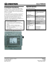
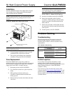
Connectors, Controls & Indicators
# CONNECTORS,
CONTROLS &
INDICATORS
DESCRIPTION
1 LINE POWER (3) 152 mm flying leads, 0.75
mm
2
, line power input
Line (brown), neutral (blue),
and ground (green/yellow)
connections
2 OUTPUT (2) 152 mm flying leads, 0.75
mm
2
, Cresnet power output
+24 VDC (red), G (black/white)
connections
Connects to “24” and “G”
connections of the Cresnet
control network, or directly to a
24 Volt DC powered Crestron
device
3 FUSE DC output fuse, T3.15AH
(5x20mm, 250V, 3.15A, time-
lag, ceramic cartridge).
4
24VDC LED
(1) green LED, indicates 24
Volts DC output, extinguishes
when fuse is blown
Setup
Important Notes
Read before installation.
• Permits: An electrical permit shall be obtained
prior to each installation.
• Codes: Install in accordance with all local and
national electrical codes.
• Wiring: Use 75°C copper wire only.
• Not suitable for Hazardous/Classified areas.
Supplied Hardware
The hardware supplied with the GLA-PWSI50 is listed in
the following table.
Supplied Hardware for the GLA-PWSI50
DESCRIPTION PART NUMBER QUANTITY
Metal, Plate, Adapter 2022080 1
Screw M3.5 x 25mm, Flat,
Phil
2023756 1
Screw, 8-32, 3/8”, Pan, Phil 2007269 4
Terminal Block, 2 Position,
Single Row
2023704 1
Terminal Block, 3 Position,
Single Row
2023705 1
4 • Wall Mount 50 Watt Cresnet Power Supply: GLA-PWSI50 Installation Guide – DOC. 6747A