


CT Power Amplifiers
page 11
CT Power Amplifiers
Operation Manual
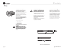
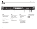
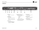
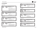
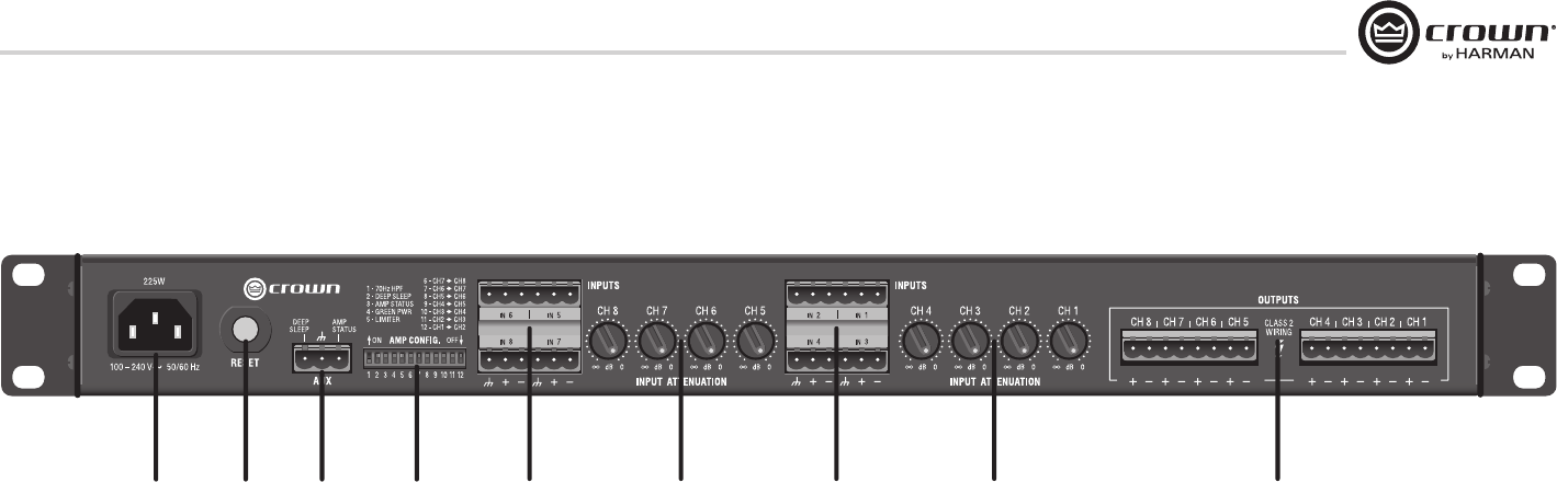
7 Back Panel
1. AC Power Inlet
• Standard IEC type 320 inlet for detachable
connector
• 100-240V
2. Reset Button/Breaker
• Push button switch
• Resets the circuit breaker that protects the power
supply
• A circuit breaker located near the IEC power inlet
protects the amplifier from excessive AC current
draw.
3. Auxiliary Connector
• 3-pin Phoenix type connector
• Allows for amp to be placed in DEEP SLEEP
mode and monitoring of AMP STATUS
(see Section 10.2)
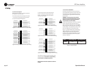
4. Amp Configuration DIP Switches (see Amp
Status/Configuration in section 10.2)
• Switches 1-5 turn specic settings on and off:
-70 Hz HPF (High Pass Filter
- see Section 8.1)
-Auto-Standby
-Amp Status
-Green Power (See Section 9.2)
-Limiter
• Switches 6-12 sends input channel audio signal
to corresponding output channel and adjacent
output channel. In four channel model, switch
6-9 are non-functional, (see section 11)
5. Amp Input Connectors
• 3-pin block connector can be used per input
• High impedance balanced
6. Channel Level Controls
• One 21-position detented rotary attenuator per
channel
• Attenuation range from -100dB to 0dB
7. Output Speaker Connector
• 4-pin Barrier block type per two channels
(2-Pin or 8-Pin Phoenix can be used)
1234 56 75 6