


Crown International, Inc.
1718 W. Mishawaka Rd.
Elkhart, IN 46517-9439
TEL: 574-294-8000
FAX: 574-294-8FAX
www.crownaudio.com
©2007 Crown Audio
®
, Inc. Specifi cations subject to change
without prior notice. Latest information available at
www.crownaudio.com. Mini-Boundary is a trademark, and
Crown and Crown Audio are registered trademarks of Crown
International.
2/07 103115-7
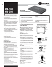
Fig. 5
Installation
Please refer to the example in Fig. 7 for installation steps.
1. Using the supplied mounting screws, mount the MB-
100 or MB-200 interface to the underside of the table in
the center.
Note: Interface should be installed within 30 ft (9.15 m) of
microphone location.
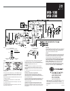
2. Plug the PTB connected to mics 1 and 2 into MIC
1/MIC 2 IN, etc.
3. Plug the PTB connected to mixer inputs 1 and 2 into
MIC 1/MIC 2 OUT, etc.
4. Plug the PTB connected to mic switches 1 and 2 into
MIC 1/MIC 2 SWITCH, etc.
MB-100
MB-200
Warranty
Crown professional microphone products are guaranteed
against malfunction from any cause for a period of three
years from date of original purchase. See enclosed war-
ranty sheet for additional information.
Service
If the microphones and interface do not function properly,
fi rst double-check the PTB wiring and switch settings as
described in this data sheet and in the microphone data
sheets. Check for correct microphone orientation.
If you determine the microphone product(s) is defective,
return the complete product in it’s orignal packaging to:
Crown Factory Service, 1718 West Mishawaka Road,
Elkhart, IN 46517-9439. A Service Return Authoriza-
tion (SRA) is required for product being sent to the
factory for service. An SRA can be completed on line at
www.crownaudio.com/support/factserv.htm. For further
assistance or technical support call 800-342-6939.
Fig. 7
MIC 1
MIC 2
MIC 3
MIC 4
MB-100 OR MB-200 INTERFACE
(UNDER TABLE)
1. If on/off switches are installed, turn each mic on in
turn and talk into it while seated at the table. The LED
should light when the mic is on (unless this function was
disabled).
2. Turn up the mixer volume control for that mic to the
desired volume.
Architects’ and Engineers’ Specifi cations
The product shall be a Crown MB-100 (or MB-200)
interface or equivalent. It shall power up to four Crown
mini-boundary mics. The interface shall be powered by 18
to 48 V phantom power.
The MB-100 shall provide programmable switching to turn
the mic on or off if desired (switches not provided). The
MB-200 interface also shall have remote switch sensing
via an optical coupler.
Pluggable terminal blocks shall be provided for micro-
phone inputs. Pluggable terminal blocks also shall be
provided for the balanced outputs on the interface, and for
remote switch sensing. The Crown MB-100 and MB-200
are specifi ed.
5. If external switch-closure sensing is being used with
the MB-200 interface, plug the PTB connected to the
sensing circuits for mics 1 and 2 into EXTERNAL SWITCH
CLOSURE SENSING (MIC 1/MIC 2), etc.
Operation
1
2
34
PTB
TO INTERFACE
“EXTERNAL SWITCH CLOSURE SENSING”
+
2K
9V
+
2K
9V
SENSING CIRCUIT
FOR MIC 2
SENSING CIRCUIT
FOR MIC 1
1 MIC 1 CIRCUIT +
2 MIC 1 CIRCUIT –
3 MIC 2 CIRCUIT +
4 MIC 2 CIRCUIT –
Fig. 6