


CPS3000PIE
6
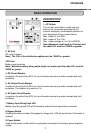
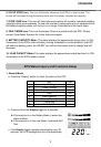
10. Power On Indicator
This LED is above the power switch. It illuminates when the utility condition is normal and
the EPS outlets are providing power, free of surges and spikes.
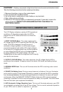
11. LCD Module Display
High resolution and intelligent LCD display shows all the EPS information with icons and
messages. For more information please check the DEFINITIONS FOR ILLUMINATED LCD
INDICATORS section.
12. LCD Display Toggle / Selected Switch
Users can monitor EPS status and set up functions using the toggle.
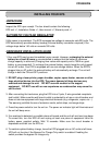
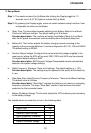
Installation Guide
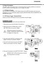
Note: The installation must be done by professionals.
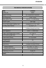
1. Remove the cover from the back of the machine.
2. Make sure both the POWER SW. and the
BATTERY SW. are turned off. (Step1)
UPS will not function if the switch is
enabled.
Enabling this switch provides
the bypass for charge only.
Step 1
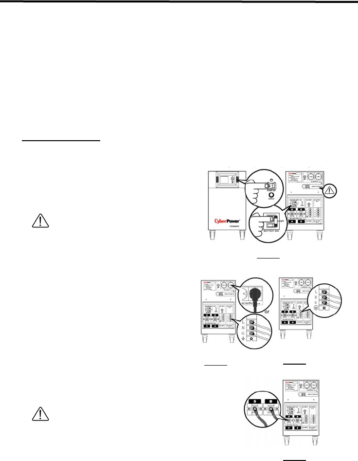
3. Connect the AC OUTPUT connections (AC
plugs or terminal connections). (Step2)
4. Connect the AC power source to AC INPUT
(Make sure AC power is off first). (Step3)
Step 3
Step 2
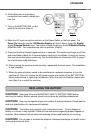
5. Connect the batteries to the BATTERY INPUT. (Step4)
WIRING FAULT LED will illuminate to indicate
the wiring polarity is reversed.
Step 4