


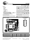
CY7C185
Document #: 38-05043 Rev. *A Page 3 of 11
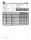
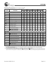
Electrical Characteristics Over the Operating Range (continued)
7C185-25 7C185-35
Parameter Description Test Conditions Min. Max. Min. Max. Unit
V
OH
Output HIGH Voltage V
CC
= Min., I
OH
= –4.0 mA 2.4 2.4 V
V
OL
Output LOW Voltage V
CC
= Min., I
OL
= 8.0 mA 0.4 0.4 V
V
IH
Input HIGH Voltage 2.2 V
CC
+
0.3V
2.2 V
CC
+
0.3V
V
V
IL
Input LOW Voltage
[3]
–0.5 0.8 –0.5 0.8 V
I
IX
Input Load Current GND ≤ V
I
≤ V
CC
–5 +5 –5 +5 µA
I
OZ
Output Leakage
Current
GND ≤ V
I
≤ V
CC
,
Output Disabled
–5 +5 –5 +5 µA
I
OS
Output Short
Circuit Current
[4]
V
CC
= Max.,
V
OUT
= GND
–300 –300 mA
I
CC
V
CC
Operating
Supply Current
V
CC
= Max.,
I
OUT
= 0 mA
100 100 mA
I
SB1
Automatic
Power-Down Current
Max. V
CC
, CE
1
≥ V
IH
or
CE
2
≤
V
IL
Min. Duty Cycle = 100%
20 20 mA
I
SB2
Automatic
Power-Down Current
Max. V
CC
, CE
1
≥ V
CC
– 0.3V
or CE
2
≤ 0.3V
V
IN
≥ V
CC
– 0.3V or V
IN
≤ 0.3V
15 15 mA
Capacitance
[5]
Parameter Description Test Conditions Max. Unit
C
IN
Input Capacitance T
A
= 25°C, f = 1 MHz,
V
CC
= 5.0V
7 pF
C
OUT
Output Capacitance 7 pF
Note:
5. Tested initially and after any design or process changes that may affect these parameters.
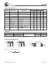
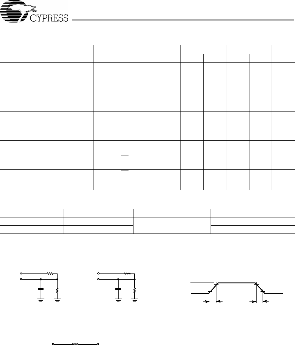
AC Test Loads and Waveforms
R1 481Ω
3.0V
5V
OUTPUT
R1 481
Ω
R2
255Ω
30 pF
GND
90%
90%
10%
≤ 5ns
≤ 5
ns
5V
OUTPUT
R2
255Ω
5
pF
(a) (b)
OUTPUT 1.73V
INCLUDING
JIG AND
SCOPE
INCLUDING
JIGAND
SCOPE
10%
Equivalent to: THÉVENIN EQUIVALENT
ALL INPUT PULSES
167Ω