


CY7C185
Document #: 38-05043 Rev. *A Page 5 of 11
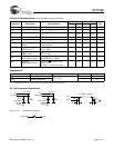
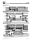
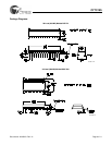
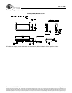
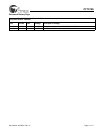
Switching Waveforms
10. Device is continuously selected. OE, CE
1
= V
IL
. CE
2
= V
IH
.
11. WE is HIGH for read cycle.
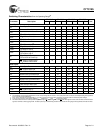
12. Data I/O is High Z if OE
= V
IH
, CE
1
= V
IH
, WE = V
IL
,
or CE
2
=V
IL
.
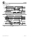
13. The internal write time of the memory is defined by the overlap of CE
1
LOW, CE
2
HIGH and WE LOW. CE
1
and WE must be LOW and CE
2
must be HIGH
to initiate write. A write can be terminated by CE
1
or WE going HIGH or CE
2
going LOW. The data input set-up and hold timing should be referenced to the
rising edge of the signal that terminates the write.
14. During this period, the I/Os are in the output state and input signals should not be applied.
ADDRESS
DATA OUT PREVIOUS DATA VALID
DATA VALID
t
RC
t
AA
t
OHA
Read Cycle No.1
[10,11]
50%
50%
DATA VALID
t
RC
t
ACE
t
DOE
t
LZOE
t
LZCE
t
PU
HIGH IMPEDANCE
IMPEDANCE
ICC
ISB
t
HZOE
t
HZCE
t
PD
OE
HIGH
DATA OUT
V
CC
SUPPLY
CURRENT
CE
1
OE
CE
2
Read Cycle No.2
[12,13]
t
HD
t
SD
t
PWE
t
SA
t
HA
t
AW
t
WC
t
HZOE
DATA
IN
VALID
CE
CE
1
OE
WE
CE
2
DATA I/O
t
SCEI
t
SCE2
ADDRESS
NOTE 14
[11,13]
Write Cycle No. 1 (WE Controlled)