


AN2034
January 16, 2009 Document No. 001-40409 Rev. *A 2
PSOC General Purpose IO
To detect single-switch closures, use the following
algorithm:
Drive all rows simultaneously and read the columns.
Drive all columns simultaneously and read the rows.
Condense this data to determine switch-closure
status.
The structure of the general purpose of each pin simplifies
this bipolar use of rows and columns. Each pin has a
digital driver that can be set up to be:
Strong drive to V
DD
and a pull down resistor to V
ss
.
Strong drive to V
ss
and a pull up resistor to V
DD
.
High Impedance
Strong drive to either V
DD
or V
ss
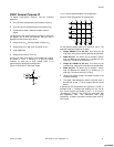
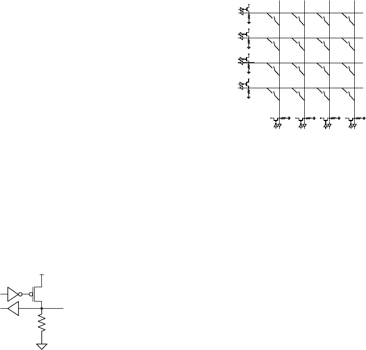
Use the pull down drive mode in the keypad scan routine,
as shown in Figure 3. Because it is also the default
condition for each pin at initial startup, there is no
requirement for special port configuration.
Figure 3. GPIO Set For Pull Down Mode
V
DD
pin
D
out
D
in
5.6 k
V
ss
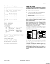
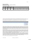
Figure 4 shows implementation of a keypad scan.
Figure 4. PSoC Architecture for Keypad Scan
C
0
C
1
C
2
C
3
R
0
R
1
R
2
R
3
P
X.0
P
X.1
P
X.2
P
X.3
P
X.4
P
X.5
P
X.6
P
X.7
For this, press example switch [2,1] (column 2, row 1). The
algorithm reads the keypad in six steps.
1.
Output b00001111 to the port. This drives all the
rows high, leaving the columns passively pulled down.
2.
Read the port. The driven pins 0 through 3 remain
high and because the switch [2,1] is closed, pin 6 is
now high. The value read is b01001111.
3.
Output b11110000 to the port. This drives all the
columns high, leaving the rows passively pulled down.
4.
Read the port. The driven pins 4 through 7 remain
high and because the switch [2,1] is closed, pin 1 is
now high. The value read is b11110010.
5. “Anding” the result of step 2 and step 4 results in the
answer b01000010.
6. The upper 4 bits decode as column 2 and the lower 4
bits decode as row 1. This is a match with the closed
switch.
A subroutine that implements this algorithm is shown in
example Code 1. It enables the reading of a four row by
four column keypad connected to port 1. It is found in
“
Keypad.asm,” located in the project file associated with
this application note. This subroutine uses eight
instructions, 15 bytes of program memory bytes, and 57-
CPU cycles.
[+] Feedback [+] Feedback