


CY14B101K
Document Number: 001-06401 Rev. *I Page 22 of 28
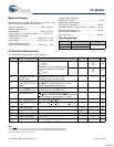
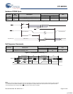
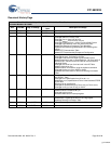
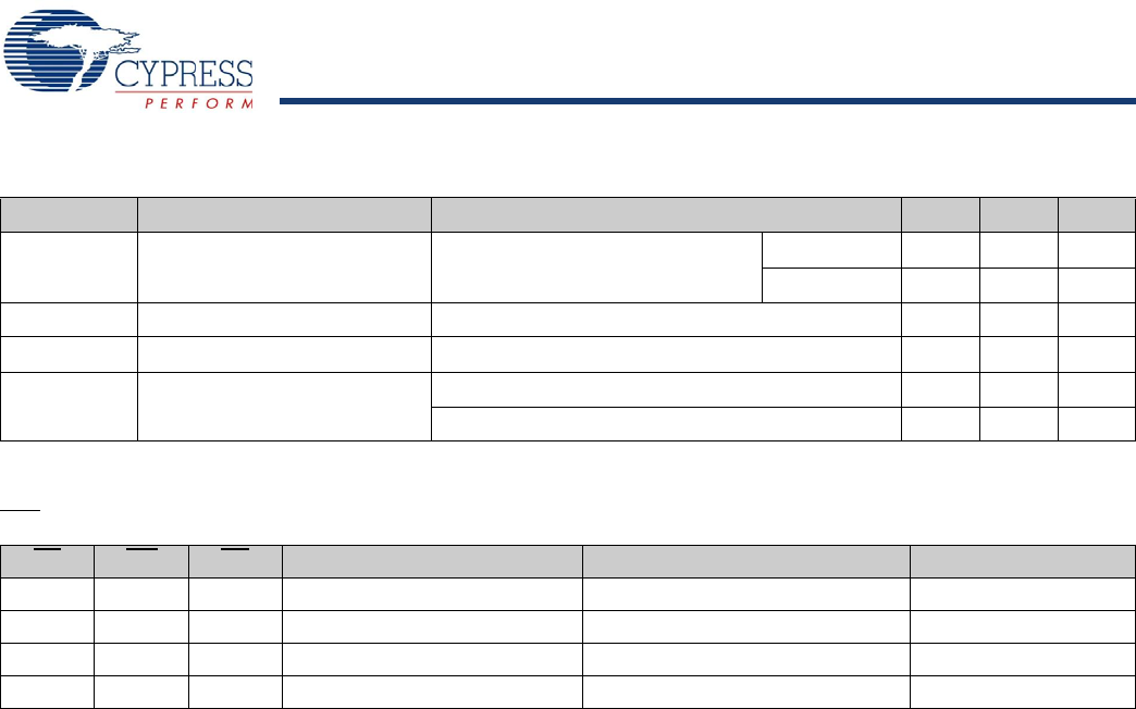
RTC Characteristics
Parameter Description Test Conditions Min Max Unit
I
BAK
[26]
RTC Backup Current Commercial 300 nA
Industrial 350 nA
V
RTCbat
[27]
RTC Battery Pin Voltage 1.8 3.3 V
V
RTCcap
[28]
RTC Capacitor Pin Voltage 1.2 2.7 V
tOCS RTC Oscillator Time to Start At Min Temperature from Power up or Enable 10 sec
At 25°C Temperature from Power up or Enable 5 sec
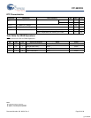
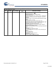
Truth Table For SRAM Operations
HSB should remain HIGH for SRAM Operations.
CE WE OE Inputs and Outputs Mode Power
H X X High Z Deselect/Power down Standby
L H L Data Out (DQ
0
–DQ
7
); Read Active
L H H High Z Output Disabled Active
L L X Data in (DQ
0
–DQ
7
); Write Active
Notes
26.From either V
RTCcap
or V
RTCbat.
27.Typical = 3.0V during normal operation.
28.Typical = 2.4V during normal operation.
[+] Feedback