CY7C291A
CY7C292A/CY7C293A
3
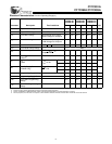
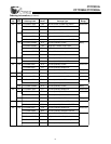
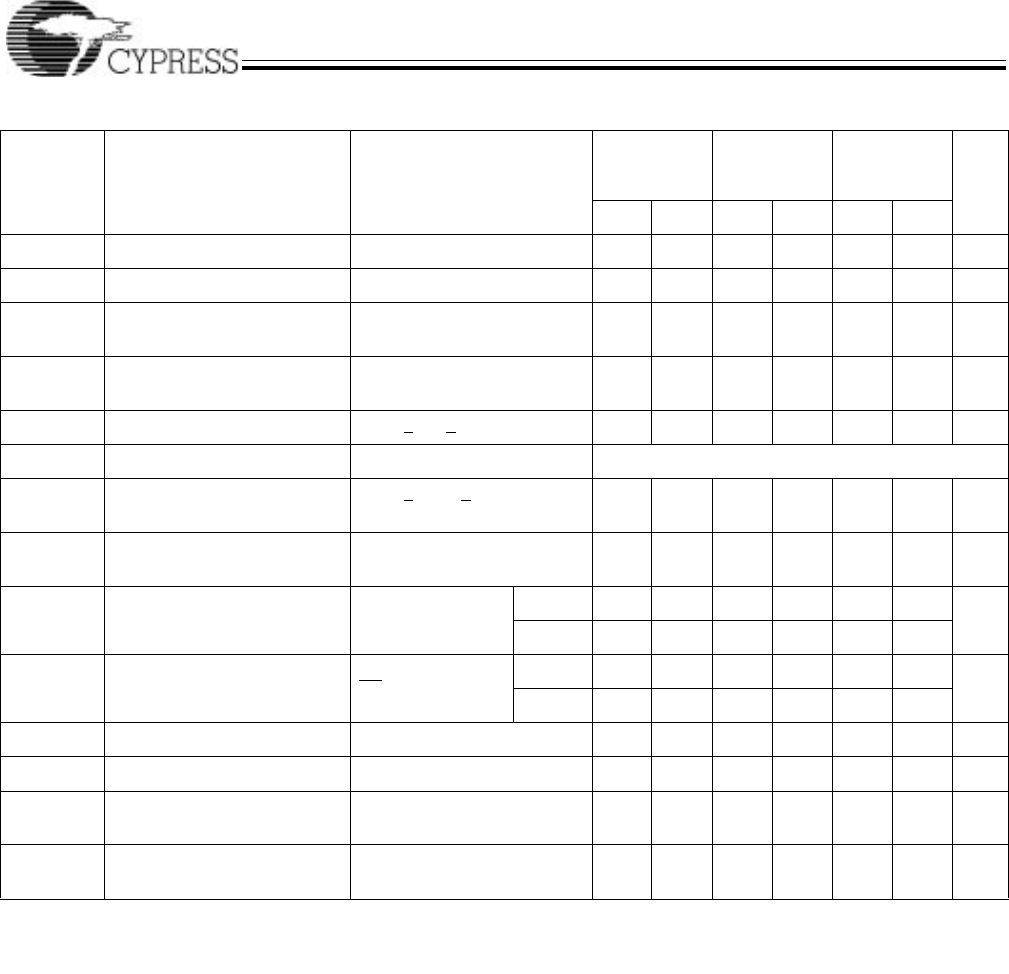
Electrical Characteristics Over the Operating Range
[3,4]
7C291A-20
7C292A-20
7C293A-20
7C291A-25
7C292A-25
7C293A-25
7C291AL-25
7C292AL-25
7C293AL-25
Parameter Description Test Conditions Min. Max. Min. Max. Min. Max. Unit
V
OH
Output HIGH Voltage V
CC
= Min., I
OH
= −4.0 mA 2.4 2.4 2.4 V
V
OL
Output LOW Voltage V
CC
= Min., I
OL
= 16.0 mA 0.4 0.4 0.4 V
V
IH
Input HIGH Voltage Guaranteed Input Logical
HIGH Voltage for All Inputs
2.0 V
CC
2.0 V
CC
2.0 V
CC
V
V
IL
Input LOW Voltage Guaranteed Input Logical
LOW Voltage for All Inputs
0.8 0.8 0.8 V
I
IX
Input Load Current GND < V
IN
< V
CC
−10 +10 −10 +10 −10 +10 µA
V
CD
Input Diode Clamp Voltage Note 4
I
OZ
Output Leakage Current GND < V
OUT
< V
CC
,
Output Disabled
−10 +10 −10 +10 −10 +10 µA
I
OS
Output Short Circuit
Current
[5]
V
CC
= Max., V
OUT
= GND −20 −90 −20 −90 −20 −90 mA
I
CC
V
CC
Operating Supply
Current
V
CC
= Max.,
I
OUT
= 0 mA
Com’l 120 90 60 mA
Mil 120
I
SB
Standby Supply Current
(7C293A Only)
V
CC
= Max.,
CS
1
= V
IH
Com’l 40 30 30 mA
Mil 40
V
PP
Programming Supply Voltage 12 13 12 13 12 13 V
I
PP
Programming Supply Current 50 50 50 mA
V
IHP
Input HIGH Programming
Voltage
3.0 3.0 3.0 V
V
ILP
Input LOW Programming
Voltage
0.4 0.4 0.4 V
Notes:
3. See the last page of this specification for Group A subgroup testing information.
4. See the “Introduction to CMOS PROMs” section of the Cypress Data Book for general information on testing.
5. For test purposes, not more than one output at a time should be shorted. Short circuit test duration should not exceed 30 seconds.


