


CY7C656x
x
PRELIMINARY
Document #: 38-08037 Rev. *D Page 9 of 23
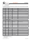
Upstream Port
17 17 D– I/O/Z Z Upstream D– Signal.
18 18 D+ I/O/Z Z Upstream D+ Signal.
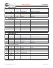
Downstream Port 1
13 13 DD–[1] I/O/Z Z Downstream D– Signal.
14 14 DD+[1] I/O/Z Z Downstream D+ Signal.
36 36 AMBER#[1] O 1 LED. Driver output for Amber LED. Port Indicator Support.
Default is Active LOW. Polarity is controlled through EEPROM.
35 35 GREEN#[1] O 1 LED. Driver output for Green LED. Port Indicator Support.
Default is Active LOW. Polarity is controlled through EEPROM.
30 30 OVR#[1] Input 1 Overcurrent Condition Detection Input. Default is Active
LOW. Polarity is controlled through EEPROM.
29 29 PWR#[1] O/Z Z Power Switch Driver Output. Default is Active LOW. Polarity
is controlled through EEPROM.
Downstream Port 2
9 9 DD–[2] I/O/Z Z Downstream D– Signal.
10 10 DD+[2] I/O/Z Z Downstream D+ Signal.
38 38 AMBER#[2] O 1 LED. Driver output for Amber LED. Port Indicator Support.
Default is Active LOW. Polarity is controlled through EEPROM.
37 37 GREEN#[2] O 1 LED. Driver output for Green LED. Port Indicator Support.
Default is Active LOW. Polarity is controlled through EEPROM.
32 32 OVR#[2] Input 1 Overcurrent Condition Detection Input. Default is Active
LOW. Polarity is controlled through EEPROM.
31 31 PWR#[2] O/Z Z Power Switch Driver Output. Default is Active LOW. Polarity
is controlled through EEPROM.
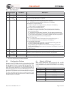
Downstream Port 3
5 - DD–[3] I/O/Z Z Downstream D– Signal.
6 - DD+[3] I/O/Z Z Downstream D+ Signal.
42 - AMBER#[3] O 1 LED. Driver output for Amber LED. Port Indicator Support.
Default is Active LOW. Polarity is controlled through EEPROM.
41 - GREEN#[3] O 1 LED. Driver output for Green LED. Port Indicator Support.
Default is Active LOW. Polarity is controlled through EEPROM.
53 - OVR#[3] Input 1 Overcurrent Condition Detection Input. Default is Active
LOW. Polarity is controlled through EEPROM.
54 - PWR#[3] O/Z Z Power Switch Driver Output. Default is Active LOW. Polarity
is controlled through EEPROM.
Downstream Port 4
1 - DD–[3] I/O/Z Z Downstream D– Signal.
2 - DD+[3] I/O/Z Z Downstream D+ Signal.
44 - AMBER#[3] O 1 LED. Driver output for Amber LED. Port Indicator Support.
Default is Active LOW. Polarity is controlled through EEPROM.
43 - GREEN#[3] O 1 LED. Driver output for Green LED. Port Indicator Support.
Default is Active LOW. Polarity is controlled through EEPROM.
51 - OVR#[3] Input 1 Overcurrent Condition Detection Input. Default is Active
LOW. Polarity is controlled through EEPROM.
52 - PWR#[3] O/Z Z Power Switch Driver Output. Default is Active LOW. Polarity
is controlled through EEPROM.
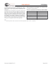
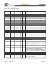
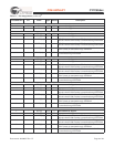
Table 7-1. Pin Assignments (continued)
[3]
CY7C65640B /
CY7C65630 Pin
CY7C65620
Pin Name Type Default Description