CY8CTST120, CY8CTMG120, CY8CTMA120
September 25, 2008 Document No. 001-49038 Rev. ** 3
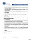
3. Invalid Flash reads may occur if Vdd is pulled to -0.5V just before power on.
PROBLEM DEFINITION
When Vdd of the device is pulled below ground just before power on, the first read from each 8K Flash
page may be corrupted. This issue does not affect Flash page 0 because it is the selected page upon
reset.
PARAMETERS AFFECTED
When Vdd is pulled below ground before power on, an internal Flash reference may deviate from its
nominal voltage. The reference deviation tends to result in the first Flash read from that page returning
0xFF. During the first read from each page, the reference is reset. This results in all future reads returning
the correct value. A short delay of 5 µs before the first real read provides time for the reference voltage to
stabilize.
WORKAROUND
To prevent an invalid Flash read, a dummy read from each Flash page must occur before use of the
pages. A delay of 5 µs must occur after the dummy read and before a real read. The dummy reads
occurs as soon as possible and must be located in Flash page 0 before a read from any other Flash
page. An example to read a byte of memory from each Flash page follows. Place it in boot.tpl and
boot.asm immediately after the ‘start:’ label.
// dummy read from each 8K Flash page
// page 1
mov A, 0x20 // MSB
mov X, 0x00 // LSB
romx
// wait at least 5 µs
mov X, 14
loop1:
dec X
jnz loop1
4. PMA Index Register fails to auto increment with CPU_Clock set to SysClk/1 (24 MHz).
PROBLEM DEFINITION
When the device is operating at 4.75 to 5.25V and the CPU_Clock is set to SysClk/1 (24 MHz), the USB
PMA Index Register may fail to increment automatically when used in an OUT endpoint configuration at
full speed. When the application program attempts to use the bReadOutEP() function, the first byte in the
PMA buffer is always returned.
PARAMETERS AFFECTED
An internal flip-flop hold problem associated with Index Register increment function. All reads of the
associated RAM originate from the first byte. The hold problem has no impact on other circuits or
functions within the device.
WORKAROUND
To make certain that the index register properly increments, set the CPU_Clock to SysClk/2 (12 MHz)
during the read of the PMA buffer. An example for the clock adjustment method is listed below.
PSoC Designer™ 4.3 User Module Workaround: PSoC Designer Release 4.3 and subsequent
releases includes a revised full speed USB User Module, which includes the revised firmware as shown in
the following example.
;;
;; 24Mhz read PMA workaround
;;
M8C_SetBank1
mov A, reg[OSC_CR0]
push A
[+] Feedback


