


COMMON FEATURES
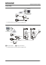
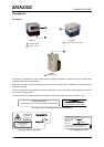
Mechanical Installation:
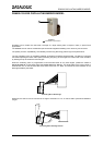
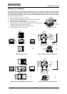
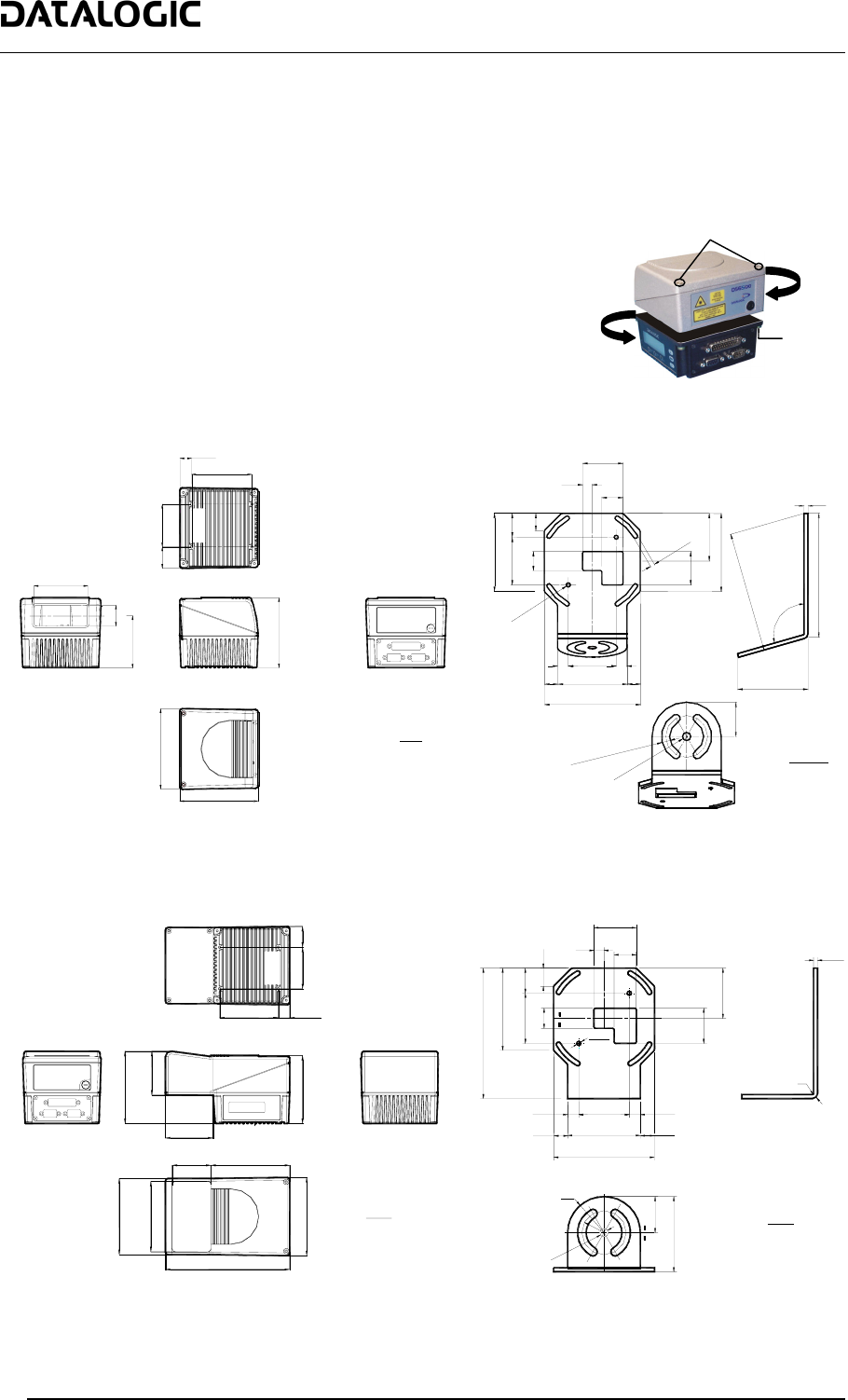
The DS6500 reader can be positioned and installed in the best way possible as a result of the Step-A-Head
TM
feature. Thanks to the separation between Head and Base, you can modify the orientation of the decoder base,
and therefore display-keypad and connector panels, while keeping the optic head in the correct reading position.
The reading head and the decoder base can be rotated independently from each other allowing the installation
even in the most critical locations.
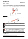
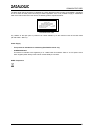
To rotate the head follow the given procedure:
1. detach the head from the base by unscrewing the four fixing screws;
2. rotate the head in the desired position;
3. loosen but don't remove the two screws on top of the head;
4. affix the head onto the base carefully aligning the four fixing screws and
progressively tightening them about half-way;
5. completely tighten the two screws on top of the head;
6. completely tighten the four fixing screws.
Step-A-Head™ Feature
4.33
4.45
110
113
99
3.90
76
30
74
2.99
1.18
2.85
85
16.5
30
3.34
0.65
60
2.36
1.18
mm
inch
==
==
82
3.22
20
0.78
50
1.96
18
0.71 N°2
25
0.98
10
0.4
22
0.86
42
1.65
Ø
4
.
1
N
°
2
Ø
0
.
1
6
N
°
2
4
.
5
N
°
4
S
L
O
T
S
0
.
1
8
N
°
4
S
L
O
T
S
82
3.22
50
1.96
35
1.37
50
1.96
72
2.83
100
3.93
4
0.1
5
130
5.12
1
2
6
4
.
9
6
106°
73.2
2.88
36
1.41
8
.
5
N
°
2
S
L
O
T
S
0
.
3
3
N
°
2
S
L
O
T
S
Ø
8
.
5
Ø
0
.
3
3
mm
inch
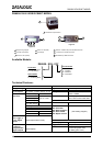
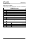
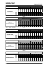
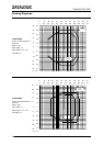
DS6500 Overall Dimensions ST-237 Mounting Bracket Overall Dimensions
3.35 0.65
2.36
1.18
3.90
2.72
4.11
2.50
4.34
4.01
2.20
4.48
4.45
7.08
mm
inch
3060
85
16.5
104.5
63.5
69
99
113
114
56
110.3
102
180
R36
R22
R5
R1
1.65
0.4
0.86
0.98
0.71
3.22
1.96
0.78
5.11
0.16
0.43
0.55
0.55
2.83
3.93
0.43
1.96
1.96
1.37
0.15
1.41
2.95
mm
inch
42
10
22
18
25
20
50
130
82
Ø4.1
14
14
72
50
100
1111
50
35
4
36
75
Ø
8
.
5
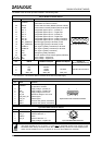
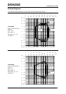
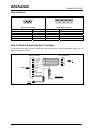
DS6500 Oscillating Mirror Model Overall Dimensions ST-210 Mounting Bracket Overall Dimensions
Fixing
Screw (4)
Head Screws
26