


DATALOGIC
3
UK/US
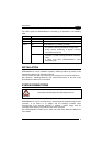
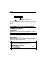
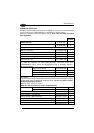
The LEDs signal the STARModem™ functioning, as described in the following
table:
LED DESCRIPTION
Power On Green constant STARModem™ is powered.
TX/RX Yellow blinking STARModem™ is receiving or transmitting data.
Off STARModem™ is working correctly. Status
Red constant
-
at startup, after firmware upload, it indicates that
the system is working with default configuration.
-
during normal functioning it signals a wrong
connection to the Host.
Red blinking
-
it blinks during a programming command
execution. In case of wrong command, it will blink
faster.
-
It blinks once when STARModem™ radio
transaction fails.
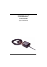
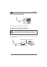
INSTALLATION
STARModem™ can be installed to operate in different positions by means of two
mounting brackets and an adjustable antenna.
The four screw holes (M4 x 5) on the body of the modem are for mechanical fixture.
See "Antenna", "Mounting Brackets" and "Overall Dimensions" at the end of this
Quick Reference Manual for more details.
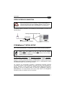
SYSTEM CONNECTIONS
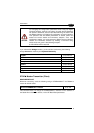
CAUTION
Connections should always be made with power off!
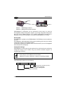
STARModem™ can be connected to the Host through the dedicated 9-pin female
connector, or by means of an adapter and the Datalogic standard cable
corresponding to the desired interface. In addition, a power supply must be
connected to the power jack provided on the same connector.
See "STARModem™ Cable Pinout" at the end of this Quick Reference Manual for
more details.