dCS Scarlatti Clock User Manual Software Issue 1.0x
June 2008
Filename: Scarlatti Clock Manual v1_0x.doc
Page 11 English version
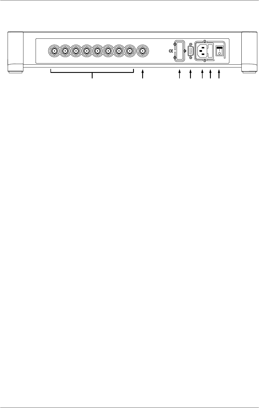
REAR PANEL
G H I J K L M
REF. IN
WORDCLOCK OUTPUTS
12345678
1394
SUC
50/60 Hz, 30W
FUSE
T 500mA L
~
Figure 3 – Rear panel
Word clock is used for synchronisation only, it does not carry digital data.
Word Clock Outputs
The unit has eight identical Word Clock Outputs (G), all of which carry standard word clock at either
44.1kHz or 48kHz.
Ref Input
The Ref In connector (H) allows the unit to be locked to an accurate external reference, such as an
atomic clock or a GPS clock. With the Coupling menu page set to TTL, the unit will lock to an external
word clock at 32, 44.1, 48, 88.2 or 96kHz. With the Coupling menu page set to Bipolar, the unit will
lock to a 10MHz reference.
As the Scarlatti Clock is a grade 1 master clock, there is nothing to be gained by locking it to a less
stable or less accurate reference!
1394 Interface
There is provision for fitting an IEEE 1394 interface (I), which may be added at a later date. As a
Master Clock does not generate or accept digital data, this will be used for control purposes only.
SUC Connector
The SUC connector (J) is an RS232 interface, primarily used to remotely control the unit during
automated testing. Please contact dCS for advice on using this interface with a household automation
system. Note that we recommend using infra-red remote control instead.
Mains inlet
Power is connected via a standard IEC320 connector (K), protected by a fuse (L) and isolated by a 2-
pole power switch (M).


