


14 About Your System
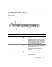
Back-Panel Features and Indicators
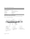
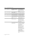
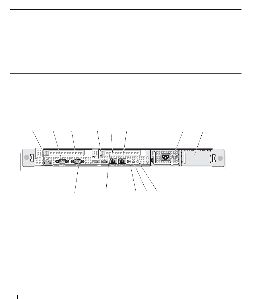
Figure 1-3 shows the controls, indicators, and connectors located on the system's back panel.
Figure 1-3. Back-Panel Features and Indicators
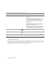
Table 1-3. Hard-Drive Indicator Patterns for RAID
Condition Drive-Status Indicator Pattern
Identify drive/preparing for removal Blinks green two times per second.
Drive ready for insertion or removal Off
Drive predicted failure Blinks green, amber, and off.
Drive failed Blinks amber four times per second.
Drive rebuilding Blinks green slowly.
Drive online Steady green.
Rebuild aborted Blinks green three seconds, amber three seconds, and off six seconds.
1 remote access controller
(optional)
2 serial connector 3 video connector
4 USB connectors (2) 5 NIC1 connector 6 NIC2 connector
7 power supply 1 8 power supply 2 (optional) 9 system status indicator
1
0
system identification button 11 system status indicator
connector
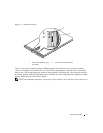
12 left PCI expansion slot (slot 2)
1
3
center PCI expansion slot
(slot 1)
7
2
1 3
8
4
5
6
9
12
13
11
10